I am going to show you about Capacitor Discharge Ignition Circuit (CDI) works.
Do you have an old motorcycle? Is it still in good condition?
I believe that many people like old cars. Because the system works less Little problem too When using the same oil In the near distance The old car is better.
We use electronics in the electrical systems of motorcycles. In the Ignition system has high importance.
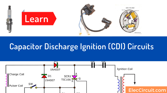
Capacitor discharge ignition (CDI) or thyristor ignition is a type of automotive electronic ignition system.
Capacitor-Discharge Ignition CDI Circuits
Sometimes you can’t buy old CDI boxes. Because the factory stopped producing Or modifications to the old model of contact breaker ignition system. It’s interesting to challenge your skills.
We have an example circuit as follows
Honda C-90

Do you miss the past?
I love it. I have used this motorcycle for many years.
Cr: Photo Hoda supper club
Learn first: How SCR works
How it works
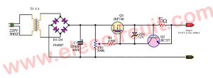
Look at the circuit diagram of CDI of C90 Honda.
The flywheel rotates. Then the magnetic field cuts the charging coil core. It makes the AC voltage at that coil flows through D3.
It will rectify from AC into DC current to charge in both C1 and C2.
Meanwhile, on the other side of the coil. The current will flow through R1 to D1 and D3 to charge C1 and C2. And the current that through R1 will lead K of SCR.
The current from lead K will flow through the R2 to the full circuit at lead G of SCR1.
The voltage drop across the R2 to trigger lead G of SCR. Makes the circuit inside SCR runs.
Next, the current will flow from C1 and C2 through lead A and K of SCR1. And it via D2 to the Primary of high voltage transformer or high volt coil.
And, when the SCR1 does not runs. There not is current to the high volt coil.
But the magnetic field of a high voltage coil collapses Cut with high voltage coil core.
Causing the induced current to go out, the secondary coil sparking at the spark plug socket.
This is during the piston stroke up to the maximum (Ignition timing)
After that, SW working, when the current flows to R1. If we press switch SW the current flows to the ground. It makes SCR does not run, the machine stops.
Recommended: 7805 regulator datasheet & pinout
Parts you will needs
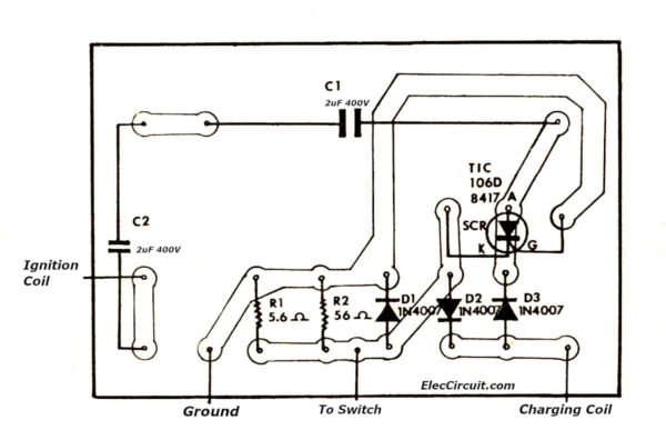
- R1: 5.6 ohms 0.5W Resistors
- R2: 56 ohms 0.5W Resistors
- D1-D3: 1N4007, 1000V 1A Diodes
- SCR1: TIC 106D SCR 5A 400V
- C1, C2: 2uF 400V, Mylar Capacitors
How to build
Look at the PCB layout guide of the C90 Honda CDI circuit.
Read others: Capacitor Discharge Ignition(CDI) Working Principle
TIC106D Pinout and Datasheet
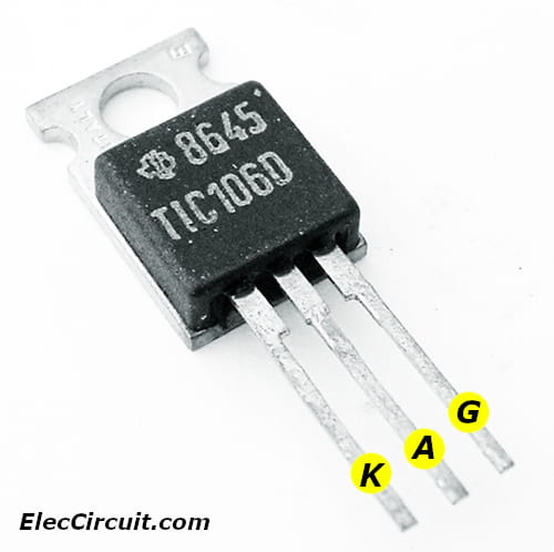
Amps: 5
Voltage: 400
Mounting: Through Hole
Lead/Terminal Type: Radial
Number Leads/Terminals: 3
Color: Black
Temperature: 110
Termination Method: Solder
Silicon Controlled Rectifiers
Reverse-Blocking Triode Thyristors
Maximum Ratings
Repetitive Peak Off-State Voltage: 400V
Repetitive Peak Reverse Voltage: 400V
Continuous On-State Current: 5.0A
Average On-State Current: 3.2A
Surge On-State Current: 30A
Peak Positive Gate Current: 0.2A
Peak Gate Power Dissipation: 1.3W
Average Gate Power Dissipation: 0.3W
Operating Temperature: -40 to 110 deg. C
Electrical Specs @ 25 deg. C Case Temperature
Repetitive Peak Off-State Current: 400uA
Repetitive Peak Reverse Current: 1.0mA
Peak On-State Voltage: 1.7V
Cr: photo TIC106D 5A 400V SCR Thyristor
Credit photo: NGK and 2-Stroke Engine Motorized Bicycle Bike CDI Ignition
Here are a few related articles you may want to read:
- 3 High Volts power supply circuits ideas
- 12V to 300V DC-DC converter circuit
- The Variable High Voltage Power Supply 0-300V
GET UPDATE VIA EMAIL
I always try to make Electronics Learning Easy.
Related Posts


I love electronics. I have been learning about them through creating simple electronic circuits or small projects. And now I am also having my children do the same. Nevertheless, I hope you found the experiences we shared on this site useful and fulfilling.
on the motocycle honda 90c.CDI circuit. where do you power the system. or it powered up at the ignition coil
hi
Pleas send me cdi dc circuit of 250cc
Motorcycle
Thanks
125 Discovere CDI Circuit Diagram
It’s not easy for my poor skill but I can see your kindness , love , passion of iron old lady.
I will see again and again your post👍 Thanks for your support.
Jangho from seoul🤟
Hi Jangho,
Thanks for your feedback. I am happy that you like this post. I also am poor in English, I am going learning English.
I like you learn electronics. It is great hobby for me, It also is good subject for my kids to study a homeschooling.
If you like or want to make or learn anything in the electronics please share with us.
Have a great day on too hot summer.
very good attempt, inspite of difficult to understand…..
please keep going….
All the best to your learning……
Hi VENUGOPALAN,
Thanks for your feedback.
LoL, I am sorry that my English is quite poor. Is it not important? Since we are happy with the electronic learning.
Apichet