If you are looking for High quality tone control circuit diagram. This may be the best choice for you. Because it uses all low noise transistors. The circuit is designed to adjust a smooth bass, and treble is soft sound with very low distortion.
Special feature
- Use low noise transistors
- Frequency response range: 20Hz-20KHz
- Total Harmonic Distortion Noise 0.001% at frequencies 20Hz-20KHz
- Maximum output voltage 14Vrms at frequencies 20Hz-20KHz
- Input sensitivity is 50mV
- The increase / decrease rate of bass : +/- 17dB at 20 Hz
- The increase / decrease rate of treble : +/- 17dB at 20KHz
Recommend: Active Bass Boost circuit using IC-741
How it works
See the audio tone control circuit below.
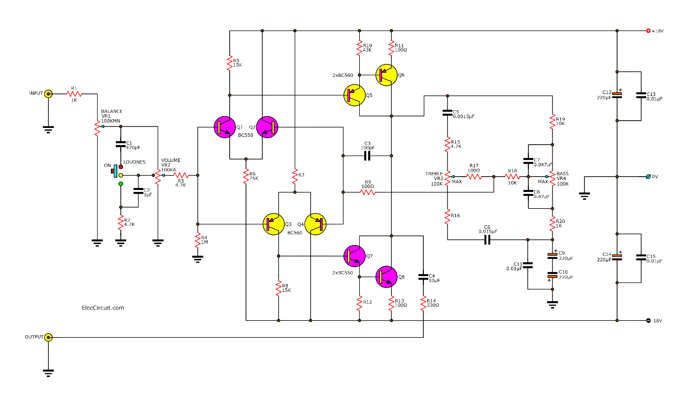
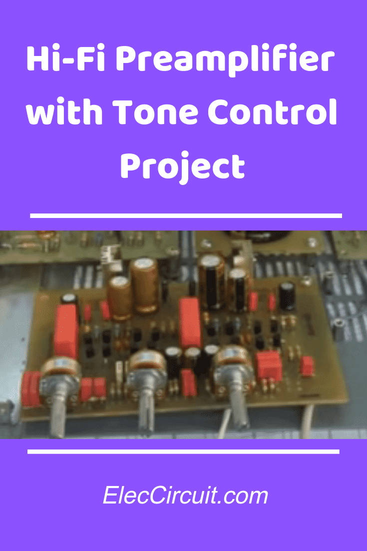
Hi-Fi Preamplifier with tone control using low noise
The transistors Q1, Q2, and Q3, Q4 are connected together as the differential amplifier. Then the output signal of lead C of Q1 and Q3, Next, sent to Q5, Q6, and Q7, Q8, amplifier set. The bias of Q5, Q6, and Q7, Q8 will be set in class A. To protect a crossover distortion. The C3 capacitor to cut high-frequency interference.
Recommended: Learn transistor works here
The output of the circuit is in lead C of Q8 through C4 and R14. For, C4 in the circuit using 10uF 100V, we may use 6.8uF 250V instead, No effect on sound quality at lead C of Q6.
The sound output is sent through R, and C circuits to adjust the sound through the middle pin of VR3 and VR4 passed through R9 to R17 and R18 lead B of Q4.
Which is negative feedback if VR is raised above, the negative feedback signal which is a lot, to make the bass and treble down. If at the center of the output signal will out of directly.
Without adjusting bass and treble. If VR is adjusted downward if the feedback is less. the bass treble will up.
This is the feedback tone control circuit that someone may need more treble was achieved by reducing the R16 from 1K to 100 ohms.
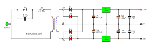
The power supply are positive and negative, by use both 18V DC regulators ICs as LM7818 and LM7918 to apply voltage at +18V and -18V
Read Also: Mini Stereo tone control circuit using IC TDA1524A
Parts you will need
1% 0.25W Resistors (Metal film types)
R1, R16, R20: 1K
R2, R3, R15: 4.7K
R4: 1M
R5, R8: 15K
R6, R7: 75K
R9, R17: 100 Ω
R10, R12: 43K
R11, R13: 100 Ωs 0.5W
R14: 330Ω
R18, R19: 10K
Metalized Polypropylene Capacitors (MKT)
C1: 470 pF 50V
C2, C20, C22: 0.1μF 63V
C3: 100 pF 50V
C4: 10μF 100V
C5: 0.0015μF 63V
C6: 0.015μF 63V
C7: 0.047μF 63V
C8: 0.47μF 63V
C9, C10: 220μF 16V
C11, C13, C15, C16: 0.01μF 63V
Electrolytic Capacitors
C12, C14: 220μF 25V
C17, C18: 2200μF 25V
C19, C20: 100μF 25V
Potentiometers
VR1: Volume 100K-MN types
VR2: Dual volume 100K-A types with center trap
VR3, VR4: Dual volume 100K-B types
Semiconductors
Q1, Q2, Q7, Q8: BC550, low noise transistors
Q3, Q4, Q5, Q6: BC560, Low noise transistors
IC1: LM7818, 18V positive DC regulators IC
IC2: LM7918, 18V negative DC regulators IC
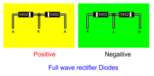
D1, D3: Positive full-wave diodes
D2, D4: Negative full-wave diodes
Recommend:
You may not buy these diodes. But you can modify them. Look at below:
Others parts
transformers, PCB, and more.
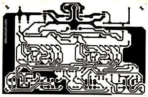
Figure 2 The PCB layouts
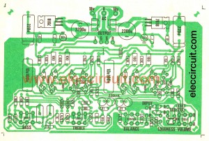
Figure 3 The components layouts
This project may not be suitable for a beginner. You should have expertise in medium electronics.
This project worked. Please watch this video.
Make: HI-Fi audio tone control project
Thanks, Jerivall good job!
Download This
All full-size images and PDF of this post are in this Ebook: Elec Circuit vol.1 below. Please support me. 🙂
Check out these related articles, too:
- 5 Tone control circuits using 4558 or NE5532
- 7 Tone control Stereo Preamplifier circuit with PCB, Low noise
Related Posts

I love electronics. I have been learning about them through creating simple electronic circuits or small projects. And now I am also having my children do the same. Nevertheless, I hope you found the experiences we shared on this site useful and fulfilling.
Excellent.
i need transistorized diagram of kvt audio booster amplipier
thank you.
is this work? pls. reply?
is this work? pls. reply cuz i like this if it’s work.
I know you can explain it better
hello, i have built some of your projects but now I would like to buy some of the pc boards that go with the projects, how can I buy the pcb’s?
can you send the simulation and pcb layout files?
Hello author! Can this be powered by +-15V instead of 18V? Has anyone built this circuit that can confirm if it works?
Here output are connected speaker??????
hi
Hi Fi audio tone control circuit using low noise transistors i see this project and i thing its a good one. i want to know how can i buy this pcb and all components and how much its cost.
Please make an audio amplifier with image and video
Please make a simple audio amplifier board with image and video please
Sure Sir i will Buy Hi Fi audio tone control circuit All Compunet pcb Also making done
I used this preamplifier here, is awesome!
https://www.youtube.com/watch?v=eZFx1fbGIDg&t=13s
thank you!
Jerivall sir send your power amp components layouts and PCB layouts Parts will need
The preamplifier has a lot of noise and I do not know how to get rid of it
Hi
I wanna build this tone control so can you, please, give me the layout file for pcb ?
Thank you !
Test preamplifier
https://m.youtube.com/watch?v=p–DWyj8oIY
It is Amazing. Your projects make me happy.
The pre amp is made with a different pcb made by me. It produces a constant hum even at volume control minimum. This hum is constant at all volume control position. The pcb is redisned and made by including a 4.7k and 220 mfd decoupling capacitor in both +ve and –ve power supply. This is included only for Q1, Q2, Q3 and for Q4. The hum remains same. when I removed the input to Q5 and Q6 ( by cutting the track to the base) the hum goes off. The amplifier is silent. That means the hum is produced in input stage or in the feed back stage. Anybody experienced the same hum. Any remedy.
Hello.Figure 1 the schematic circuit diagram the input resistor in the circuit is 1k, and on Figure 3 The components layouts 4.7k, is this an error?
Sir sir Kit wad bass treble circuit ropise Whatsab no 03120062820 Imtiaz Nasir Pakistan
Hi,
I’m very thankful for your interest in the project. Unfortunately, we do not have a PCB service.
As Mr. Jerivall has built it so nice sound. You also can do it.
Hai sir i will try the board but i not find this ( k a K and a k a) near 2200u this is ic tell me sir
Hi,
Please look at:https://www.eleccircuit.com/tda2030-stereo-amplifier-circuit/#Full_wave_rectifier_diodes
How to modify to Full wave Rectifier diodes.
Thanks very much
Jerivall sir send your power amp components layouts and PCB layouts Parts will need
yes i try and it work
Thank you for visiting our website.
I’m glad you were able to successfully.
experiment with these circuits. 🙂
Hi Sir can you please tell me how you calculate the value of resistor ? I’m looking forward to understand more about the circuit
Hi,
It is very interesting. My dad and I are learning to design this circuit, or to learn how to calculate various devices. My dad said that it was usually a very complicated theory. Which, of course, is difficult for my brain to learn. But my dad tried to make it easy for me. We have now tested the methods we have calculated and have developed a circuit that works to our satisfaction. In the future we will share this experience we have learned with you. Hopefully it will be useful for you and you will continue to follow us. 🙂