These are the passive tone control circuit. You can adjust audio both bass and treble without increasing the signals at output.
We use only basic components R and C. They perform filter low or high frequency.
It is easy to build and cheap. We do not need to use any power supply. Next, its output can be increased more power with a power amplifier immediately.
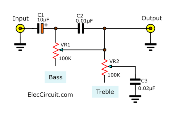
Simplest tone control circuit
See in the circuit below. It is simplest tone control circuit. We can adjust bass and treble easily with rotate VR1 and VR2 to control the tone of music.
Better quality passive tone control circuit
For bass-treble tone control that has better working. It is designed by Mr Grommes. Use more R and C devices. As shown in the general standard circuit in the figure below.
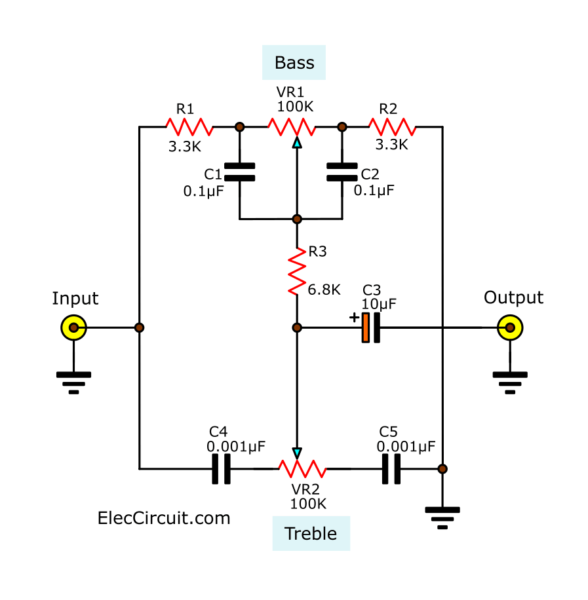
The value of components in the circuit. They may be increased or decreased according to individual tastes who like the bass-treble of the music differently.
- Capacitor C1 and C2 and resistor R2 affect the bass. If the C2 value is used more. For example from 0.068uF to 0.1uF. And reduce R2 down from 1.5K to 1K will increase the bass level.
- Increasing or decreasing C3 and C4 will affect the treble signal more or less, respectively. As shown in the circuit figure below. Which is the same circuit But the level of the equipment is different.


Not only that see other passive tone control circuit below.
Make a passive tone control circuit
See the circuit that you can use it works well.
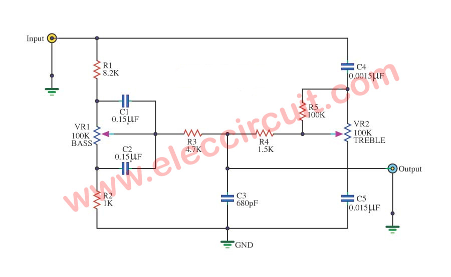
How it works
When we feed a input signal to input of the circuit. The sound signal will come in to separate in 2 the ways.
The first way will via to a low pass filter. It includes R1, C1, C2, and R2. And it has the VR1 be adjusted the low frequency ratio gain or the bass.
The second way a signal will come to a high pass frequency filter section. They include C4, R5, C5, and VR2 be adjusted the value of
high frequency or treble.
The signal from both low and high pass frequency filter flow through R3 and R4 to the output.
Then, have C3 cleans the noise signals goes out away.
The Shopping list
0.25W Resistors, tolerance: 5%
R1: 8.2K
R2: 1K
R3: 4.7K
R4: 1.5K
R5: 100K
Ceramic Capacitors
C1,C2: 0.015µF 50V
C4, C5: 0.0015µF 50V
C3: 680pF 50V
Potentiometers
VR1, VR2: 100K
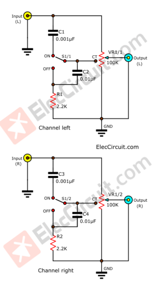
Audio Loudness Control circuit
If your main amplifiers. But the sound is not clear as low treble and little bass. We offer an easy way. Using less equipment. You create a very simple
Audio loudness control circuit used to add bass. More during the normal listening levels.
It is a passive circuit and does not use the power supply.
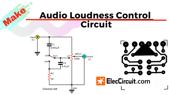
When the input signal into. Switch S1 is an option to use open (ON) using loudness control. Off (OFF) to use a bypass. When the switch S1 to the ON position the signal will flow through C1(0.001uF), C2(0.01uF) and R1(2K).
This will serve as a low pass filter circuit.VR1 is adjusted by the strength of the signal to the output.VR1-100K Linear Potentiometer, which uses the volume type with a central bar (Center Tap) only.
The output of the circuit will be connected to the region to pre-tone next step.
Note: All capacitors use Ceramic Capacitor or Mylar Capacitor them low cost
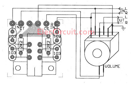
How to build
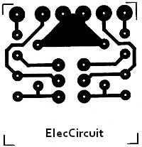
This circuit has a few components so you can builds easily as Figure 2 make PCB layout and putting all components on PCB and connecting to your audio system.
The PCB and components layout of this projects.
See also, you may like these circuit too.
- Super pre tone control project using LF353
- Bass Treble Tone control circuit diagram
- 3 Tone control circuits using op-amp NE5532
- Active Bass Booster circuit using 741

I love electronics. I have been learning about them through creating simple electronic circuits or small projects. And now I am also having my children do the same. Nevertheless, I hope you found the experiences we shared on this site useful and fulfilling.
#Audio Loudness control circuit
Hello, How can I buy some of your pc boards?
#Audio Loudness control circuit
Do you sell these in Kit form or sell the PC boards?
Beautiful
#Audio Loudness control circuit
Circuit diagrams
nice grammar keep it up!
#Audio Loudness control circuit
Hi there, what is the potentiometer with a centralmtap.?
Does it have 4 connections per channel.?
I only know potmeters with 3 connections…
Thanks
Hello Ad,
Thanks for your visit. Yes, 4 terminal Potentiometer (per channel). It might be hard to find nowadays. I found here: https://amzn.to/3d01l5X
How should I connect this for a quad amplifier circuit?
Hello Kishok,
Thanks for your visit. How are you?
This circuit is very simple circuit. But it may low signal output. If you use a main power amplifier. It cannot drive high amplifier.
You may use other circuits with preamplifier circuit. For example:
https://www.eleccircuit.com/tone-control-circuit-low-noise/
https://www.eleccircuit.com/hi-fi-preamplifier-with-tone-controls-project-circuit/
https://www.eleccircuit.com/low-noise-pre-tone-control-circuit-using-ne55532/
Thanks again
Apichet
Can I connect this input to the 3.5mm audio jack and the output to the input of the amplifier circuit?
Hi,
You may try it. I think it is low sound but you may like it for small amplifier.
If you get a good sound. Please tell me again.
I like to help you.
Thanks
Hello,
VR should be LIN or LOG ??
Thanks for help !!!
Hell Rafael
You should use LIN or 100K(B) Potentiometer.
Thanks
Are Linear potentiometers not normally marked (A)?
Hello Bent Arnoldsen,
Thanks for your visiting my site.
Yes, You can use the potentiometer type B for bass and treble.
But at volume, should be typed (A). Because the volume of the sound can be adjusted more smoothly.
Have a good day
Apichet
Hello
could you please double check your shopping list?
there is a difference between the values of capacitors in the shopping list and the last figure.
For example, in the figure the value of C1 and C2 is 0.15uf and C4 is 0.0015uf but in the shopping list you said that C1=C2=C3= 0.015 uf.
Thank you in advance.
Hello Arash,
Thanks for visiting my site.
Oh… I am sorry for the shopping list mistakes.
Have a good day.
#Audio Loudness control circuit
I try this diagram don’t work on my Amp. Very low sound almost no sound.
#Audio Loudness control circuit
Hi, I just build the loudness circuit for my amp. It sound great. But I find that the bass is a bit too powerful. May I know what value to chance & where to change to reduce the bass a little? Thanks.
Hello Lum,
Thanks for your visit to my site.
I am sorry! This circuit is low sound output. Because it is without an amplifier circuit inside.
You may try other preamplifiers with control circuits.
https://www.eleccircuit.com/hi-fi-preamplifier-with-tone-controls-project-circuit/
https://www.eleccircuit.com/three-circuits-of-preamp-tone-controls-by-ne5532/
https://www.eleccircuit.com/tone-control-circuit-low-noise/
Hello,
Can you tell what low and high frequencies are affected with this circuit?
#Audio Loudness control circuit
Do any of the values have to change if you are using a 50k or 25K volume control. If you are using a VC with 4 connectors (2 rows of 4 connectors), which tap do you use?
#Audio Loudness control circuit
Hello, is this diagram for one audio channel? Do I need 2 for stereo?
Regards, Bert
Hi,
Thank you for visiting our website.
I would like to express my opinion on behalf of my Dad.
We have improved the circuit into a stereo system.
So, that it will be convenient for you to build this circuit.
It’s quite simple. 🙂
#Audio Loudness control
Great schematic – works very well. But I’ve done some modifications: Replaced resistors with 3.3KOhm and capacitors with 47n and 470pf.
Hello,
Thanks for your feedback. Your experience was great. I am glad it sounded as good as you wanted.