This is voltage to frequency converter circuit that uses the CA3130 OP-Amp ICs. The output is linearity Of changing is very well up to 0.5%. Also, they has the Temperature coefficient of less than 0.01% per degree Celsius.
How Voltage to Frequency Converter Works
In the circuit diagram below. The IC1 acts as the frequency generator. It is controlled by voltage. Suppose, first the output voltage of IC1 is + 15V. Then, the C1 charges a current through D3, R4, and VR1. With constant value equal to (R4 + VR1) C1.
Until voltage at inverting input of IC1 exceeds at a non-inverting input. Which three resistors R1, R2, and R3 set the voltage at the non-inverting pin. Now, the output of IC1 is changing to 0 volts. But the voltage drops across at non-inverting input are about 5V. Because of hysteresis voltage from R3.
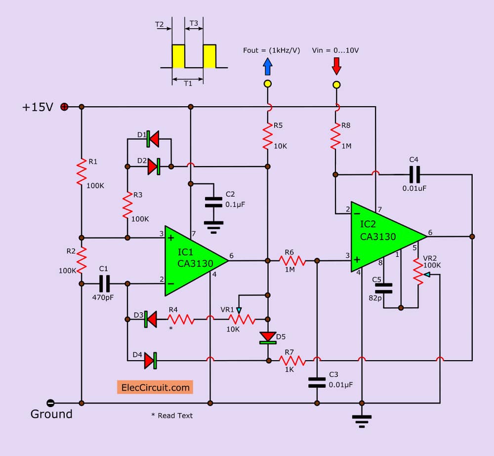
Then, C1 will start discharge to the output of IC2 through R7. Until, the voltage at inverting input less than 5V. Next, the output of IC1 will increase up to +15V again.
And the original process begins again. The output waveform of IC1 include of the positive pulse that time period equal T2 and Spacing between pulses is equal to T3, which change by the output voltage of IC2
After that R6 and C3 filters the output voltage at pin 3 of IC2, V2. It is the smooth DC voltage. Then, this voltage equals the average value of the waveform of IC1.
Because T2 is constant, V2 has a value suitable. It generates the T1 or Suitable for a frequency generator from IC1. The input voltage Vin comes to inverting input of IC2 that act as the integrator-comparator circuit.
Note:
R4 = 180K Resistor
D1 to D5 = 1N4148 Diode
If Vin less than V2, the output of IC2 will be the positive ramp waveform, C1 will discharge slowly cause the T1 range as long times. And reduce the value of V2 down, but if V1 more than V2, the output of IC2 will be the negative ramp waveform (into zero).
Next, cause C1 discharges faster, the time range T1 so lower down, and when V1 equal V2 voltage output of IC2 will It is a constant, unchanging.
When the circuit to output a constant, then (Vin = V2) means that V1 is the proper frequencies produced. Because Conditions of the circuit is Frequency is the appropriate value of V2. So V1 is appropriate as well.
A good temperature stability, Because the temperature coefficient of D3 and D4, make charging to C3 change.
We fix it put diode features same D3 and D4 (D1 and D2) in series with R3, To compensate for temperature changes according to the non-inverting input pin of IC1.
VR2 adjusts the offset voltage to IC2 to output voltage no error.
The P1 is used to fine adjust the changing the voltage to frequency, The values obtained were in the range of 1 kHz per volts.
Note: This circuit is just ideas and I never test them. So you should build carefully it.
Related Posts


I love electronics. I have been learning about them through creating simple electronic circuits or small projects. And now I am also having my children do the same. Nevertheless, I hope you found the experiences we shared on this site useful and fulfilling.
Awesome, Thanks.
kalo tegangan inputny 3,7volt oout ny brapa gan ??