The Flyback transformer tester circuit of the televisions that the result is a simple, easy and cheap to build.
My friend is TV repairman colors – black and white. He said the repairing on the flyback is very difficult. Because it has a large size, high voltage source. So it is very dangerous.

When the assumption that it is damaged. It’s not easy to testing. Need to know what the working principle, and a great tool. To reduce expenses and time.
Its internal structure is mostly coiled over. Which are often damaged in many cases?
Lack. lamps look like it. We are able to measure with a multimeter. Set the value of the resistance. If there is no resistance to it. In the lack of bad.
But if bad in other ways, which is not very often is Short Round. He said that the cause may be due to the use it gets hot. The coil can be melt fused together. But we can not check that. In this way it was. Because when measured with plain meters. It is resistant to normal.
When they solve the problem by buying a new trial flyback replaced. That it is not wise Because of it is expensive and difficult to replace. Sometimes satellite TV owners will want to urgent.
We suggested he try to build this flyback transformers circuit. It has the advantage of a simple, cheap and easy to use. Because of the things he used to have, almost would not have buy more it. And very cheap compared to the flyback one.
Learn: How to use 555 timer circuits
How it works
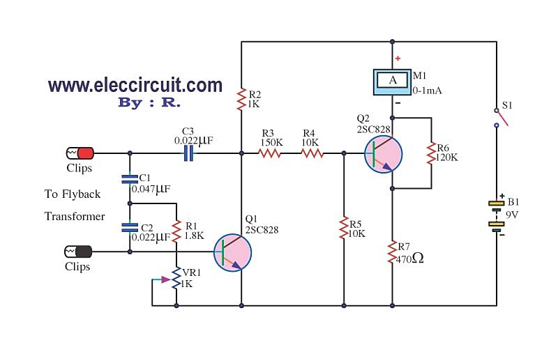
As shown below, as a simple circuit with the two most important components.
- The oscillator circuit uses a transistor Q1 (2SC828) is base works with three capacitors C1, C2, C3 and three resistor R1, R2, VR1, to produce a sine wave frequency.
- The current amplifier and detect circuits has transistor Q2 (C828) is used to increase the signal to works with four resistor R3, R4, R5, R6, And R7 is used to limit current to the amp meter.
At least, if you choose the amp meter that uses the lower current, so use a resistance R7 increase up.
The part of this circuit
Q1, Q2: 2SC828 or 2SC2240 low noise, 30V 100mA NPN transistor
C1: 0.047uF 63V Polyester Capacitor
C2, C3: 0.022uF 63V Polyester Capacitor
R1: 1.8K 1/4W Resistor
R2: 1K 1/4W Resistor
R3: 150K 1/4W Resistor
R4, R5: 10K 1/4W Resistor
R6: 120K 1/4W Resistor
R7: 470 ohm 1/4W Resistor
M1: Meter 1mA
This circuit requires enough power supply. Do you have this one? If you do not have it. Look:Learn Many Power supply circuits
Customization and bring to used
To Begin with, place two probes at twin pins of the good flyback transformer. Second, turn on switch S1. If you can read the current approximately 0.1mA, the oscillator circuit is not working.
Then, adjust VR1 to reduce value its steadily with the observe the meter. If you read value is 0.4 mA, it indicates that the oscillator circuit already starts.
Next, you try to bring the probe to touch together (Short together) to see that the meter needles falls down. Show that, this flyback transformer Short certain oscillator will stop running.
We can measure transformer to the other, must adjust VR1 to meter reading is 0.6mA. It normally, the meter needle will wiggle back and forth a little bit. But if the transformer is “Short Round”, the meter needle will down.
Keep reading:
- 1.5V to 5V boost converter circuit for microcomputer
- 555 timer Pulse Generator circuits | astable mode
- How to test a diode with tester circuit
Related Posts

I love electronics. I have been learning about them through creating simple electronic circuits or small projects. And now I am also having my children do the same. Nevertheless, I hope you found the experiences we shared on this site useful and fulfilling.


While using this circuit, you can take a short piece of wire and make one turn through an open place on the flyback. If you short your one turn together, the flyback should stop oscillating. If the circuit shows it’s oscillating, and continues to oscillate after you short the one turn, that means the circuit has been set to too sensitive.
Great Little Tester to have around especially if you’re repairing TV sets or Monitors.
Pls sir, what are the alternative for for the 0.022UF and 0.047UF polyester capacitor
image of RV1
Hi,jammit
Thanks for your feedback.
Hi,MR.OHM
Thanks your feedback my friend.
Hi,A. M. Uganda
Thanks for your feedback.
I am sorry not understand you say clearly.
Hi,anhky
Thanks for your feedback.
VR1 is normally potentiometer.
it maybe work ?
yes or no
i need video of the Flyback transformer tester circuit using 2SC828
are you sure (Flyback transformer tester circuit using 2SC828) it work 😀
Hi,anhky
Thanks for your feedback.
Yes, This circuit worked.
can i could replace transistors MJE13009 ?
can i could replace transistors MJE13009
hi,anhky
I don’t know it will work.
Because it is high power npn transistor.
but may work if you change others parts.
Good luck.
🙂
I do not know how to use RV1
I accomplished all circuits but also VR1 (normally potentiometer)
circuit i not work