This is a gain clone amplifier circuit that sound quality is very good. We use an IC as the main parts are LM3875, produced by the National Semiconductor.
This IC is the highest power amplifier 56 watts at 8 ohms speaker. As well as IC amplifier Gain Card that very famous.
General Features of the LM3875
It is less than 0.03% THD + N distortion in the audio frequency range 20 Hz-20KHz with DC voltage from +/- 20V to 40V. The IC includes circuitry to block a lot.
For example…
- Protect a spike or block the signal of the power circuit
- Short circuit protection
- And output over-voltage protection circuit, out of voltage or overload.
So it is almost a complete IC without additional circuitry, thus leading to yet more user-friendly and convenient.
It’s also a low noise IC by there is an S/N value or signal-to-noise ratio higher up than 95dB (min)
According to Figure 1 Appearance
and the inside circuit as Figure 2
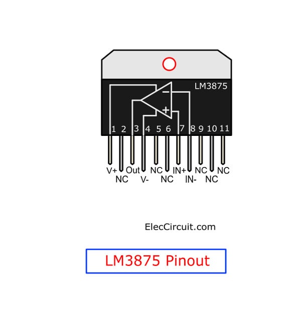
Figure 1: The LM3875 Pinout
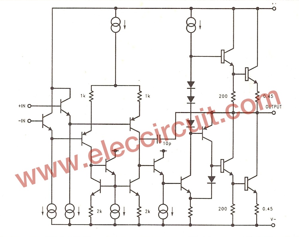
Figure 2: The internal circuit in LM3875
How it works
In Figure, 3 This project is non-inverting amplifier circuit. Most devices within the IC almost all.
There are some little further: the power supply, network at output speaker and fuse to protect the spike signal of external devices Each one has the following function.
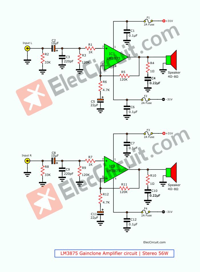
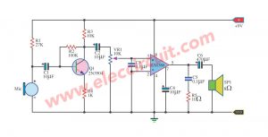
Figure 3 the schematic diagram
The left-channel audio signal is connected to the input, to resistor R2 act as set, the impedance of the circuit is 33K through the coupling capacitor C2.
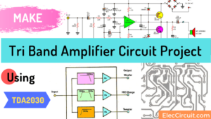
Related: Tri Band Amplifier Circuit Project
The signal into the ultrasonic filter circuit. Which includes capacitor C3 and resistor R3 and R1. To protect the radio noise signal and attenuate RF signal is lower before the signal will into pin 7.
Thus this has high gain up to 25 times.
The gain derived from the input signal back to the input through both resistors R5 and R6 is calculated by the equation (1 + R5 / R6).
The capacitor C5 is connected to R6 to help lower frequency to -3dB at frequency about 10Hz.
The sound signal is amplified and then come out the pin 3 of IC. Before leaving Speaker shall pass to the Zobel network circuit.
They include R4 and C4 To solve the problem with the load capacity and maintain stability at high frequency.
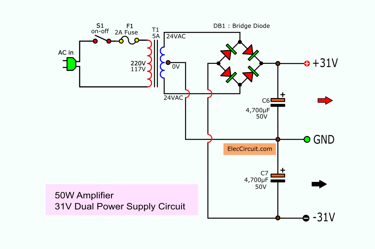
For, the supply Transformer reduced voltage AC power. From high-voltage 220VAC into a lower voltage at low voltage 24-0-24 VAC current 5A.
This low voltage is sent to the bridge rectifier BD1 to approximately + 31V DC power adapter with a capacitor C13 and C14 filter the voltage smoothing, and The DC voltage at this time.
It is a supply voltage to this amplifier circuit.
Here are a few related articles you may want to read:
- 40W transistor audio amplifier circuit with PCB
- A simple video amplifier circuit
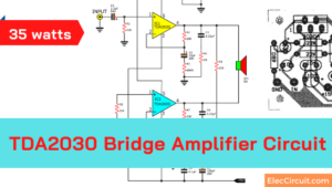
- TDA2030 transistor amp circuit with PCB

How it builds
Since this project is hard for a beginner. Is it easy?
Sure, some want to build it by oneself. Please email me. It is a large file PCB layout.
Recommended: Quick Learn Basic Electronic Components
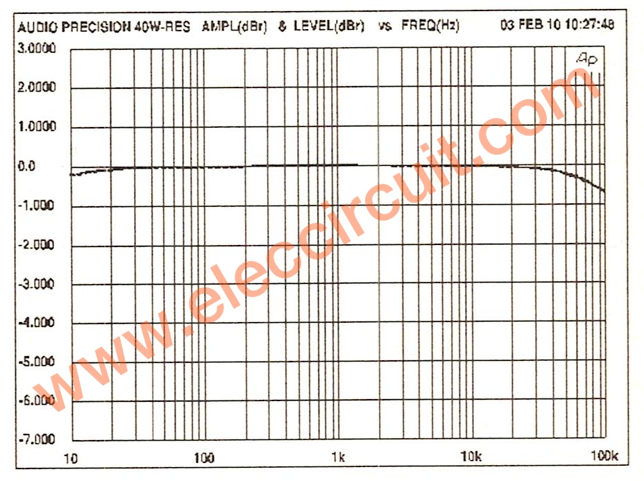
This project has the Frequency response and the total harmonic distortion: THD is lowest, as Figure 6 very good Frequency response.
Other Circuits
Even more importantly. You can build other circuits better than this.
Here are a few related posts you may find helpful, too:
- Power Supply for Audio Amplifier , multiple output 12V, 15V, 35V
- LM386 stereo amplifier in bridge 2 watts
- 200 watt MOSFET amplifier circuit class G

I love electronics. I have been learning about them through creating simple electronic circuits or small projects. And now I am also having my children do the same. Nevertheless, I hope you found the experiences we shared on this site useful and fulfilling.

This circuit is very good for a small hifi system in house, with medium overall specifications. Watch out at power supply , it’s very simplistic. You can use a linear power supply to take at next level this circuit. It will improve the Power Supply Power Rejection (PSRR).
Great.
Hello, thank you for this circuit. My only question is how to establish volume control? Where could one build this into the circuit, and what size audio taper in ohms ?
Hello;
I saw different resistor value,Could you please write to me correct value..
R6: 47K and R12: 4.7K
Which is correct ?
Thank you…
“Hello,” my dear friend,
R6 and R12: 4.7K
Have a good day
Thanks
Apichet
Can i use 220VAC-25VAC transformer instead of 220vac-24vac?
According to the IC datasheet, DC voltage from +/- 20V to 40V can be used. When you use a 220VAC-25VAC transformer, the output voltage is about 35V, so it’s no more than the specification of this IC. However, my dad and I have never tried this circuit. So it can cause mistakes. but we believe you can. 🙂