Imagine Your house is mini or you are a beginner or getting a hurry. You love music and want a hobby with Electronics. How do you make feel better? You should build a tidy amplifier. Use LM1875 circuits.
Why?
It gives a 20W audio amplifier on Class AB type. Voltage Gain is 90dB. Low Harmonic Distortion Noise is 0.015%, 1KHz, 8 ohms. And Wide supply range 16V-60V at 4A.
Not only that, but It also has Protection for short circuits to the ground and thermal shutdown.
General Description
The LM1875 is a wide power amplifier with very low distortion and high-quality efficiency for audio applications. It gives power is 20 watts into a 4 ohms or 8 ohms load on 25V power supplies.
Its amplifiers circuits are designed to working with a minimum of external parts.
When overload it has protection consists of both internal current limit and thermal shutdown.
Other features are high gain, fast slew rate and wide bandwidth, large output voltage swing, high current capability, and a very wide supply range.
See below.
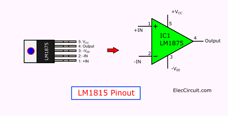
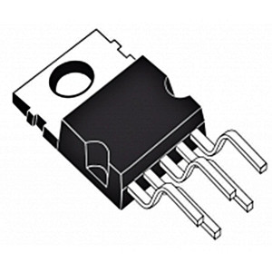
Look at LM1875 Pinout below
What is more?
Look at its basic circuit.
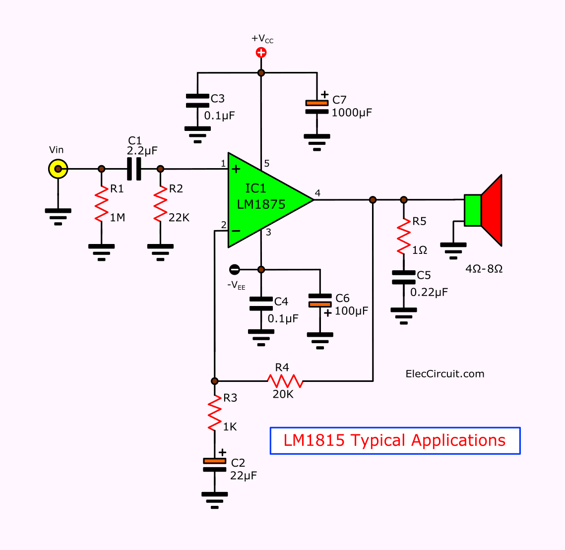
In Figure 1 as Connection Diagram and Typical Applications of LM1875
The amplifier is internally compensated and stable for gains of 10 or greater.
Specification Value
- Up to 30 watts/channel output power
- Maximum Load Resistance: 4 to 8 Ohm
- Maximum Input Bias Current: 2uA@±25V
- Avo typically 90 dB.
- Low harmonic Distortion Noise : 0.015% @ 1KHz @ 8 ohms @ 20 watts.
- Maximum Input Offset Voltage: 15mV@±25V
- Wide power bandwidth: 70KHz
- High current capability: 4A.
- Maximum Working Temp: 150°C
- Maximum Supply Current: 100mA@±25V
- Wide supply range: 16V-60V
The Power supply type are single and dual, there is detail as follow.
- Minimum Single Supply Voltage: 16V
- Typical Single Supply Voltage: 18V|24V|28V
- Maximum Single Supply Voltage: 60V
- Minimum Dual Supply Voltage: ±8V
- Typical Dual Supply Voltage: ±9V|±12V|±15V|±18V|±24V|±28V
- Maximum Dual Supply Voltage: ±30V
- 94dB ripple rejection
- Typical Gain Bandwidth Product 5.5MHz
- Typical Supply Current: 70mA at ±25V
- Protection for AC and DC short circuits to ground
- Thermal protection with parole circuit.
- Internal output protection diodes.
- Plastic power package: TO-220
We use it’s on the High-performance audio systems, Bridge amplifiers, Stereo phonographs, Servo amplifiers, Instrument systems and more.
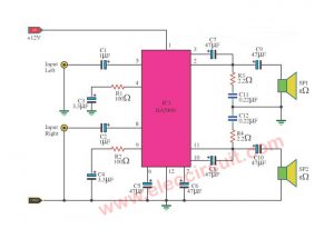
LM1875 Hi-Fi OCL Audio Amplifier
All want a great sound that no significant distortion. You know that the OCL amplifier mode does not lose all frequency of sound. Especially the bass!
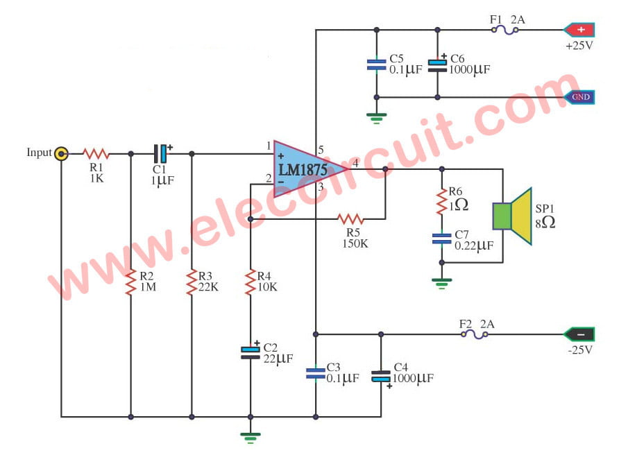
Look at 25 watts OCL Audio Amplifier circuit.
Circuit ideas that you can get useful
This circuit uses a positive, negative and ground power supply to get the audio signal with both halves of the signal swing, positive and negative. It causes sound out crystal clear. In OCL amplifier style.
Here is the step by step process.
Enter a signal to the input. The audio flows through R1, R2, C1, and R3 to limit the audio signal appropriately. And limit the noise to the ground.
Then, sends a signal to the input pin 1 of IC1. It is a non-inverting pin. Or the non-return phase. And output pin 4 to access the speakers.
Next, eliminate the noise in the output signal to the ground using the R6.
While another part of the audio output pin 4 of the integrated circuit will feedback through R5 to pin 2.
And both resistors R4 and R5 determine the rate of boost up. We can calculate from R5/R4.
In this the gain equal to 15 times.
Also, C2 keeps this circuit has a response to high frequencies better.
What is more?
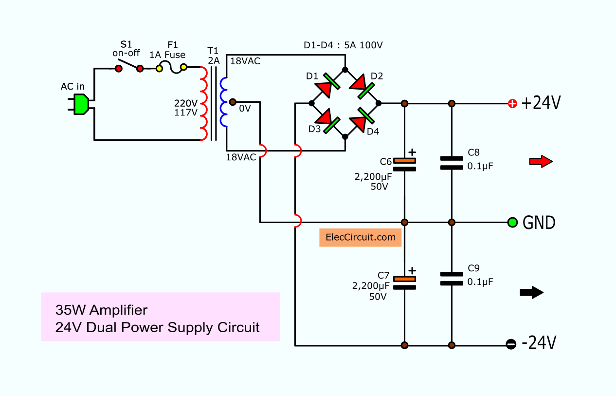
This circuit requires a 24V dual power supply circuit.
Look:
It gives a power of 2A max.
Here is the mono amplifier. If you want stereo you should change more current up to 4A transformer. And use C6, C7 are 4700uF 50V.
If you like to learn about the unregulated power supply
LM1875-24V Dual power supply circuit
LM1875 OTL Amplifier circuit 30 watts
If you need to have a high power amplifier in small size. I suggest this project, It has powered drive output up 30 watts, by low noise and Low distortion. And easy to build because use a few devices. But is good sound energy worth the cheaper.
The circuit principle
The LM1875T is Amplifier IC model of National Semiconductor.
- A body on Supplier Package: TO-220, Pin Count to use is 5 pin.
- This IC is built by High technology monolithic type makes very low Total Harmonic Distortion Noise less than 1% (0.015%@8Ohm@20W) the quality of sound.
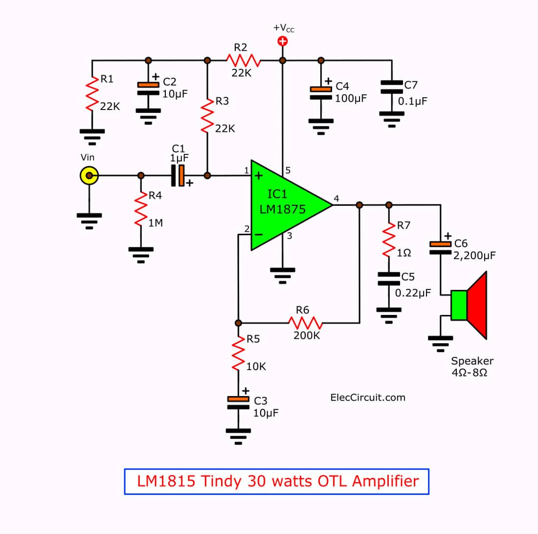
Figure 1 Tiny 30 watts OTL amplifier using LM1875
They can use with DC power supply wide range between 16 volts to 60 volts and can use both dual and single voltage. In this project use, the single voltage supply is Positive and Ground. As Figure 1
The voltage of the power supply will have an effect on the power of the IC.
If we enter the DC voltage supply of 50 volts, the IC has powered up to 25 watts.
Use the impedance load between 4 ohms to 8 ohms.
But we use the maximum signal supply voltage up to 60 volts, and power output up to 30 watts. Which impedance load 8 ohms.
This IC model IC have the protection system with the Maximum Operating Temperature in a range -65 to 150°C, So widly use, but if you use fan to IC heatsink to reduce heat of them so very well.
In circuit diagram form in signal characteristics is non inverting input signals. in to the input. There are R4-resistor adjust input impedance and coupling through the C1-capacitor in to amplifier section inside the IC1.
Thus R1 and C1 will set the frequency of input signal, by R1, C2 filter the noise (D-coupling), from power supply to protect noise through the input.
What is more?
Both R5, R6-resistors are connected in feedback form, and act as adjusting gain of circuit. But R7 and C5 are used to bypass or through high noise frequency to ground. To To ensure the quality of sound output improves. And there is C6 coupling signal out to the output ( Load) The value that use to good sound quality even more. and also protect DC voltage leak to load.
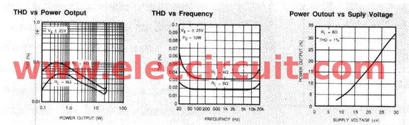
Figure 2 the graph shows various features of the LM1875
Figure 2 is graph to show the comparin various feture of LM1875T-IC as table 2 (A) show compere between Distortion percent of signal (THD) and power watts at output. Which IC drive over 20 watts. The resistor load of 8 ohms. To the harmonic distortion less than load 4 ohms.
Table 2 (B) show compare between the values of harmonic distortion and frequency of signal at output. By in range frequency about 80 Hz up to about 10 KHz Harmonic distortion in the stable and have lower average between both load about 0.025%.
In table 2 (C) show compere output power and voltage of power supply at load 8 ohms. Which if we use voltage up to 30 volts will be watts power output about 32 watts.
This amplifier use high voltage power supply and highe current up to 3-4 Amperes. This helps improve the stability of the circuit. Resulting in better sound quality as well.
You may also like these:
- High Current 12V 30A Power Supply
- TDA2020 OCL HI-FI Power Amplifier
- 40W Transistor Amplifier with PCB
How to build LM1875 project
The amplifier circuit as Figure 1 that is single side or mono system only. Thus if build on stereo system you have to builds two sets.
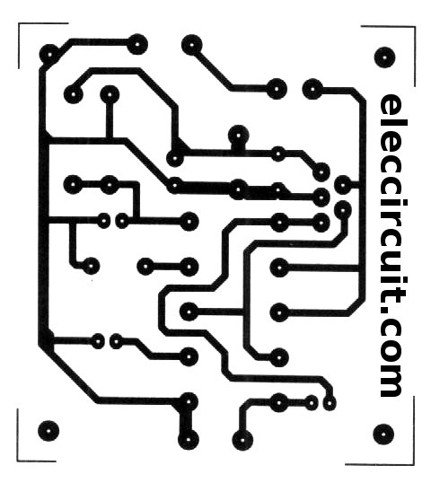
To begin with find all components before, so make an Actual-size,Single-sided copper PCB layout as Figure 3. Then assemble all parts to PCB as Figure 4 so easy.
Figure 3 Actual-size,Single-sided copper PCB layout
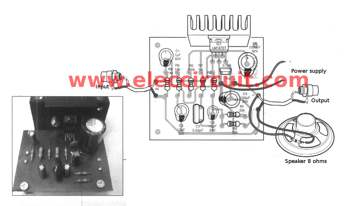
Figure 4 the components layout.
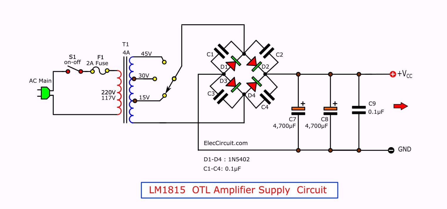
For who not have DC power supply voltage : 50-60 volts. Current around 3-4 amperes. To try circuit in Figure 5
Testing and application
First, apply good signal (CD, tuner) to input, If have the tone control and low volume with it better, the Connected input signal is applied to the project. and speaker of 4-8 ohms sized about 30 watts to output.
The components list
Resistors size : 0.5 watts +5%
R1-R3: 22K
R4: 1M
R5: 10K
R6: 200K
R7: 1 ohm
Capacitors
C1: 1uF 50V, Electrolytic
C2, C3: 10uF 50V, Electrolytic
C4: 100uF 50V, Electrolytic
C5: 0.22uF 50V, Mylar
C6: 2,200uF 50V, Electrolytic
C7: 0.1uF 50V, Ceramic
Others
Heatsink
The speaker size of 4-8 ohms 30W
PCB, terminal, wires, etc.
Conclusion
Is it less loud for you? You want louder sound, right? Sure, a higher watts amplifier may make you more enjoyable.
55 watts Stereo Amplifier using LM3875
I love electronics. I have been learning about them through creating simple electronic circuits or small projects. And now I am also having my children do the same. Nevertheless, I hope you found the experiences we shared on this site useful and fulfilling.

Wanting to use the LM1875 to amplify up to 60 kcs.
Is this possible?
Do I need to alter any components?
Hello Steele Braden,
Thanks for your visit to my site.
I don’t understand, what do you mean ” 60 kcs”?
Do you mean 60 watts power output?
In normal it can power 30 watts (4 ohms speaker)per channel.
If you use power transistors to increase power up it may be 50 watts up.
I hope you finish your amplifier project.
Have a great day.