This is the 200 watt MOSFET amplifier circuit on Class G with PCB. It is suitable for the PA system. Which it is a high end for all your working.
You can read more feature:
– maximum RMS output power: 200 watts at load 8 ohms or 360 watts at the load 4 ohms.
– Frequency response range: 10Hz.-150kHz.
– Minimum Harmonic distortion: 0.008%.
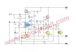
How it works
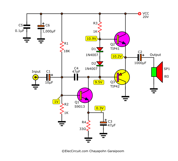
The input signal comes to C1 into the base of Q1 that is connected with Q2 as the differential amplifier circuit.
Then, this signal is increased to the section 2 (Q3, Q4).
Next, the signal flows to the transistors driver(Q12, Q13), to drive the output transistors (Q15, Q16).
Finally, the output signal is a drive to the loudspeaker.
Recommended: High MOSFET Power Amplifier
↓ 200 watt MOSFET Amplifier circuit↓
In lower signal range, both transistors Q14 and Q15 will do not work. When it is the peak signal rage, this signal will come to D3, D4 to bias Q10 and Q11 run.
As a result, the MOSFET Q14 and Q17 also work. This cause the power supply 2 that have the higher voltage up to 100 volts to the amplifier section.
This feature makes the peak signals are not trimmed like the other general amplifiers.
Here are the highlights of the class G amplifier. Because all transistors do not need to work hard all the time.
So, Reduce energy loss and heat of the output power transistors better than the other high power amplifiers.
Keep Reading:

How to build it
First of all, You should buy all components as lists below. Then, make the PCB below. It is actual-size of Single-sided Copper PCB layout.

Copper PCB layout
Then, assemble the parts on the PCB as Components layout. You should check carefully several times. Because this project has more details. If the error it would have been severely damaged.

Components layout
Next, screw the power transistors and power MOSFET on the heat sink. By using mica sheets and the silicone pad to aid cooling. It is attached to the heat sink, tighten the screws firmly.
Remember! Do not short circuit the transistor to the heat sink.
Measuring MOSFET amplifier
When we finish assembling the project. Then, short circuit the input to the ground. Next, apply the power to the project.
After that, measure a current that flows through the positive of the 100 volts power supply. We should read the maximum current of about 20 mA.
Then, measure a current at the positive of the 40 volts supply and also have maximum current about 20 mA.
Next, use the voltmeter measure voltage between both base of Q11 and Q12, then adjust VR1 until reading the voltage about 2.6V to 2.7V.
Lastly, measure at the speaker terminal it must be zero only. Now this amplifier ready to use.
MOSFET Amplifier power supply
We should use the transformer minimum current 4A (per channel), and the secondary coil must have center trap at 70 and 31 volts as below.

200 watts amplifier power supply circuit
At the filter capacitors should connect the low capacitors to reduce the oscillation of circuit in high frequencies, we use about 0.033uF to 0.1uF.
Parts you will need
Power Supply
- T1: transformer (70-31-0-31-70V)__4A./CH.
- D1, D2: BRIDGE Diode 25A 200V
- C1, C2: 8200uF 120V Electrolytic Capacitors
- C3, C4, C5, C6: 0.033uF 250V, Polyester Capacitor
- C7, C8: 10,000uF 50V, Electrolytic Capacitors
MOSFET Main Amplifer
Transistors
- Q1, Q2, Q1: 2SA872 or similar
- Q3, Q4: BC648 or similar
- Q5, Q6, Q7, Q8: 2SD668 or similar
- Q9: BD139 or similar
- Q10: 2SC1775 or similar
- Q12: 2SD669 or similar
- Q13: 2SB649 or similar
- Q14: 2SK176 or similar
- Q15: 2SD551, 2SC2608 or similar
- Q16: 2SB681, 2SA1117 or similar
- Q17: 2SJ56 or similar
Polyester Capacitor
- C1, C6: 1uF 63V
- C2: 100pF 63V
- C3: 0.1uF 63V
- C4: _22pF 63V
- C9, C13: 1pF 63V
- C10: 4pF 63V
- C11: 0.22uF 63V
- C12: 390pF 63V
- C14, C21: 0.47uF 63V
- C15, C16: 0.0022uF 63V
- C7, C22: 75pF 63V
Electrolytic Capacitors
- C5: 220uF 50V
- C8: 100uF 25V
- C17, C18: 100uF 250V
Diodes
- D1, D2, D3: 1N4148, 75V 150mA Diodes
- D4, D6: 1N5403____400V 3A Diodes
- D5: ZD 15V_1W Zener diodes
0.5 watts resistors tolerance: 1%
- R1: 470K
- R2: 2.2K
- R3: 12K
- R4: 33K
- R5, R6, R7, R15: 68K
- R17, R18: 68K
- R8: 56Ω
- R9, R10: 1.8K
- R11: 10K
- R12: 2.7K
- R13, R16: 1.2K
- R14: 270Ω
- R19, R30, R32: 100Ω
- R20: 200Ω
- R21, R27: 470Ω
- R22, R26: 150Ω
- R25, R28: 220Ω
- R33: 39K
- R29, R34: 10K, 1W Resistors tolerance: 1%
- R31: 33Ω, 5W Resistors tolerance: 5%
- R24, R35: 0.3Ω, 5W Resistors tolerance: 5%
- R36: 47Ω, 5W Resistors tolerance: 5%
- VR1: 1K PRESET
GET UPDATE VIA EMAIL
I always try to make Electronics Learning Easy.
Related Posts

I love electronics. I have been learning about them through creating simple electronic circuits or small projects. And now I am also having my children do the same. Nevertheless, I hope you found the experiences we shared on this site useful and fulfilling.
Muito Bom Esses Projetos de Amplificador.
Hi, Zelino
Thanks for your feedback.
this is 100% woking or tested sir?..coz i wnna try this sir..TNX
nice circute
Sir can u send me video on this same circuit for how to build and parts that required for this
where can i find an appropriate tone control for this pre amp, i mean the plan is to make an integrated amp.
where can i procure the semiconducters or appropriate substitution as these semiconductors seem to be difficult to get.
Can someone please give me the size of the PCB. thanks in advance!
Hello. I see that you don’t update your page too often. I know that writing content is boring and time consuming.
But did you know that there is a tool that allows you to create new posts
using existing content (from article directories or other pages from your niche)?
And it does it very well. The new posts are unique and pass the copyscape test.
You should try miftolo’s tools
I like
Hello there, first of all I would like to thank you for this 200 watts Amp well detailed like this.
If you can kindly assist by sending me the dimensions of the PCB and component layout I will be very grateful.
Thanks in advance