This is Power bank mobile charger circuit project. When we need to take the mobile phone to the outdoors that no electrical outlet. To backup energy when need a portable mobile phone. It uses a low dropout voltage, high-efficiency, LM1086.
When electricity outlet to plug in to recharge a battery. And if thety often use mobile phones. Which moderate power consumption.
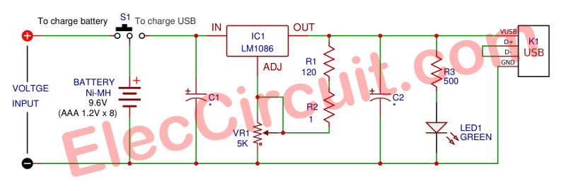
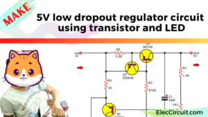
Figure 1 is the Portable power pack circuit
If the batteries run out still not certain. Many people chose to carry a backed up battery. And another alternative is buying the Portable power pack In order to solve this problem.
But the price is highly reasonable when sit think we as an electronics amateur. You can build it yourself is not difficult to use the simple principle of dc regulator circuit, which Many people are already familiar. If interested, you can see that it is really simple.
How it works
Figure 1 is a proper circuit of this project. That is characteristics of the standard circuit as a type of common adjustable voltage regulator IC, that We familiar with each other well. They are designed with IC low dropout voltage.
It is well known that the most common regulator IC there will have Voltage across itself in Figure 2. That compares two numbers between regulator ICs. The first number is the IC-7805 has a lower drop across in/out is 2.5V, But LM1086 has under 1.5V. We are familiar with the LM1086-IC number.
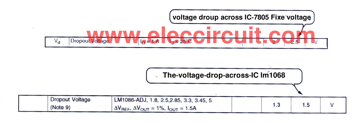
Figure 2 is, for example, compare information the voltage across input/out of IC-7805 and LM1086
Read also: How to use 7805 voltage regulator
Why is selecting the LM1086 (low dropout volts IC)
From the information that shows on the datasheet. We will see that in LM1086-regulator IC has a very low voltage drop across.
This helps reduce the loss of energy from the voltage drop across it, While it is applied will pull a load current is very low too.
So there is a temperature lower than IC-7805 or LM317.
But there is a disadvantage that this IC type expensive than a general regulator IC. However, it has many advantages. It should be applied extremely. We like it because smaller than LM317 suitable for packet small size projects.
The S1-switch serves as select between charging voltage into a our backup battery-B1. Which can make with packing the battery Ni-MH of 1.2 volts current 1,000 mA on AAA type, to pack 8 batteries together, until it has a voltage of 9.6 volts.
We can charge this battery by using this project: Automatic ni-mh battery charger can make by yourself Since if is not has a control circuit that batteries are very hot. So should use the battery charger that build-in current controller, it is well and cheap.
When B1-battery is full if we need to use this backup battery to charge all various mobile phones. Next, we slide the S1-switch at the portion the Charge USB.
While on this place the voltage from B1(the backup battery) will be connected to the adjustable output voltage regulator as main is LM1086 (1.5A Low Dropout Positive Regulators IC). It has the same pin-out as standard LM317.
And can use a replacement as well. In that case, do not buy the LM1086. But do not qualify for low dropout voltage only.
The voltage from B1-battery will be entered into the input pin of IC1.
Then, there are C1-capacitor serve as a filter of the input voltage. And then, the output will have C2 served as similar.
The C2 should use the tantalum electrolyte capacitor type to great stability of output.
Both resistors R1 and R2 will be connected with VR1-potentiometer to adjust the output of IC1 to suitable to charge with Compatible devices from voltage port USB 5 volts. Which cannot exceed the tolerances +/- 5% from voltage level 5 volts.
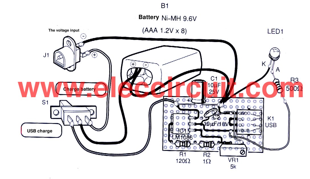
Figure 3 is a assemble on the universal PCB board.
The output voltage that passed through the adjusting completely, will be sent to the K1 which is a port USB type A female form. For a charge of the external mobile device. And LED1 is used into indicator power-on of this project that is charging.
How it builds
Since this project is not used many components so can assemble on the universal PCB board. The wiring for circuit wiring and various components can view the example in figure 3. What to look out for is the polarity of the capacitor correctly. The pin of the IC is not an error. Should not be connected until the battery will certainly
GET UPDATE VIA EMAIL
I always try to make Electronics Learning Easy.
Related Posts
I love electronic circuit. I will collect a lot circuit electronic for teach my son and are useful for everyone.
Intent: to measure temperature distribution in silicon wafer treated with ion beam having a temp of 400degC placed inside the vacuum Chamber.
I wanted to integrate a circuit in the wafer itself so that it will measure temperature and transfer through a wireless communiation., may be bluetooth , IR etc.,
Or else it has to store the value. once the wafer is removed from vaccum by ROBOT then we have to retrieve the datas of temperature distribution.
I am working on the circuit.
Let me know if you have any queries to help me out.
Expexting your help to get it resolved.
Regards
Meheboob
temperature in a vacuum for a isulator inside a chamber which will have upto 400degC.
I asked you in this ckt at the end of “THE VOLTAGE INPUT” is we connect the ac supply or not
HOW TO MAKE CURRENT FROM POTATO WHAT ARE THE MAJOR MATERIALS REQUIRED
Can I use in the place of variable resistor into fixed resistor
how many voltage input is j1
I am learning electronic engineering so please help me for my major.
How to know if the power bank is full?