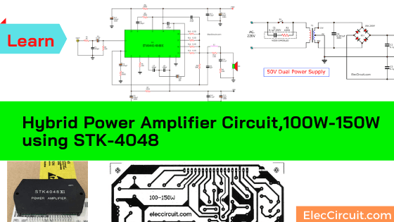
If you are looking for a high-quality 100w-150w amplifier with low distortion. This may be a good choice. Some called it STK power amplifier series are hybrid IC of Sanyo.
Why is it interesting?
STK power amplifier circuit has low distortion of about 0.003% only.
The heart working of this circuit is the hybrid IC of Sanyo. It is usually found in expensive audio equipment.
ICs STK watts list
The ICs that use has three wattages to choose the number below.
STK4044XI = 100W
STK4046XI = 120W
STK4048XI = 150W
As the following table shows the features of the IC table 1.
IC family STK4044XI, STK4048XI have developed various models from STK4044II, STK4044V, and STK4044X respectively, Until the STK4044XI model we use in this circuit.
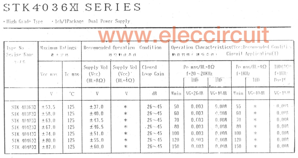
Table 1 the datasheet of STK4036XI Series
The IC has the internal circuit different due to improved, which external circuit can be used instead of directly.
For this reason, we say that. Be careful before buying it Some may be subjected to such a low-quality version of the ICA STK4044II.
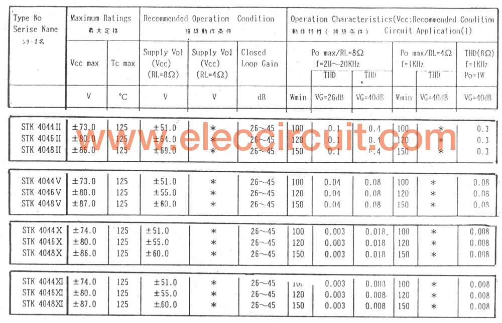
Table 2 compare STK4036II and STK4036XI
Consider the comparison feature of Table 2, you will know the difference.
See real STK4048XI. You may buy it at Amazon.com
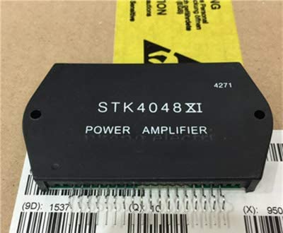
Figure 1 will see that the internal circuit in STK4044XI and STK4048XI that will be have the beginning circuits same together will be different than the output section of STK4048XI will have two output transistors to parallel, allowing for increased wattages up to 150 watts.
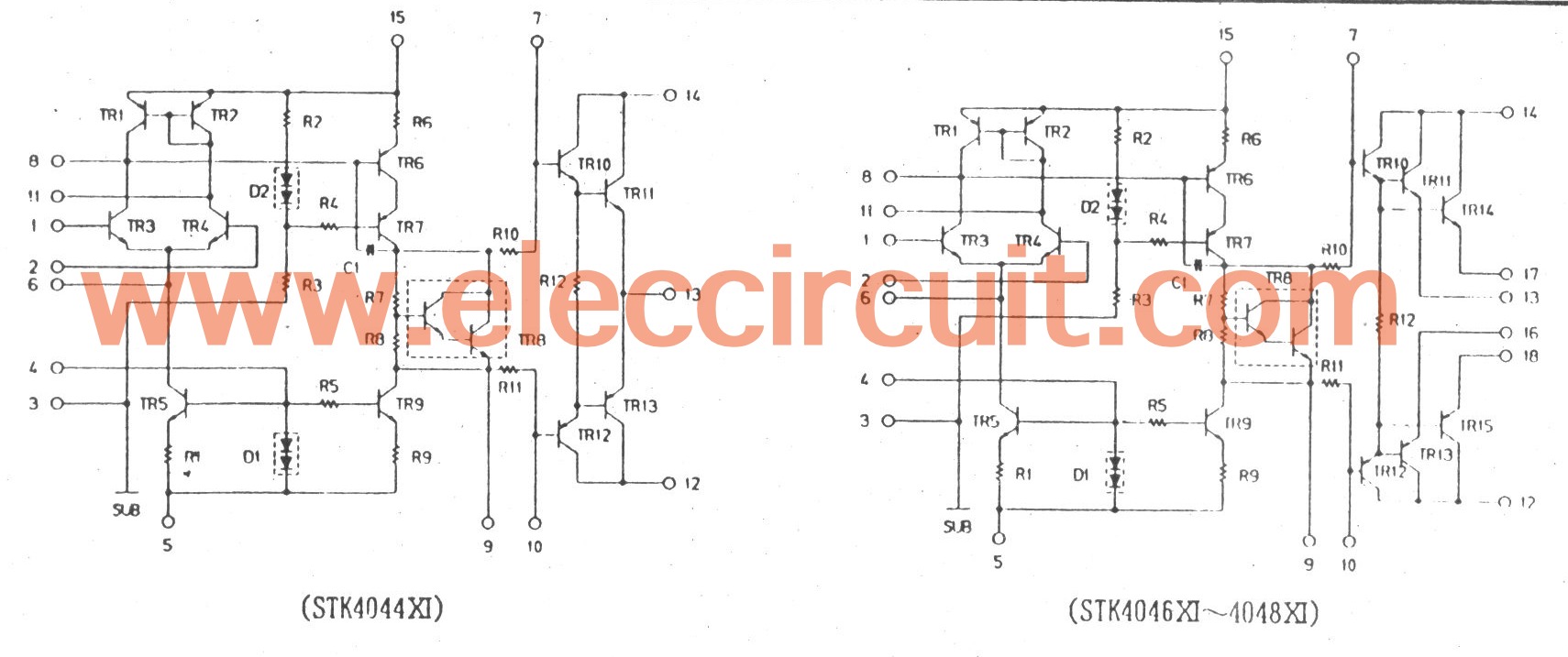
See inside IC STK amplifier circuit
Thus, at 15 pins of first will be same, but in this circuit have the output and input pins are 3 pins only as figure
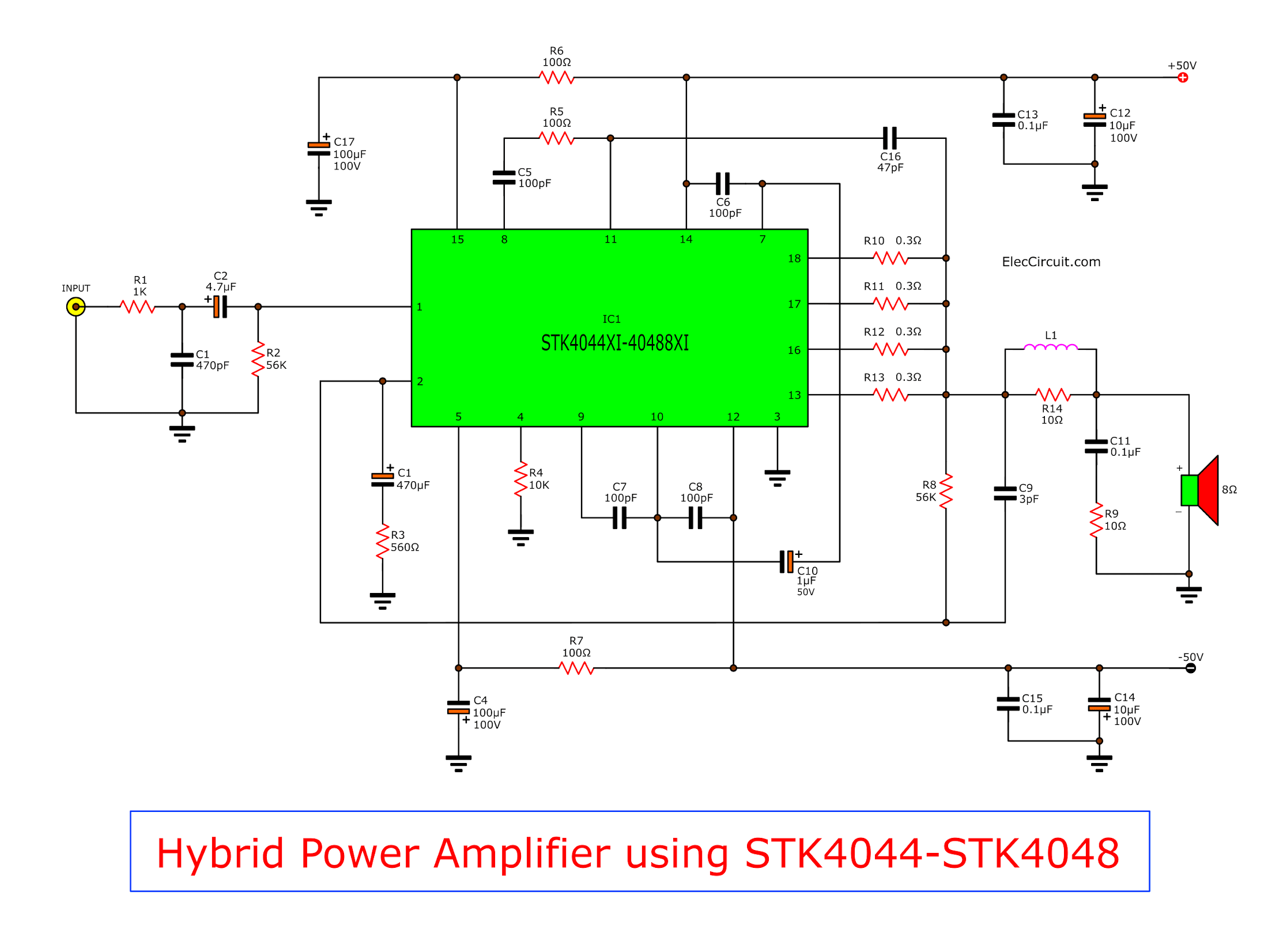
See The real schematic circuit diagram of this project
In the PCB layout and components layout which we are designed to be shared by the three numbers as above, if the number STK4044XI released them float the 16-18 pins.
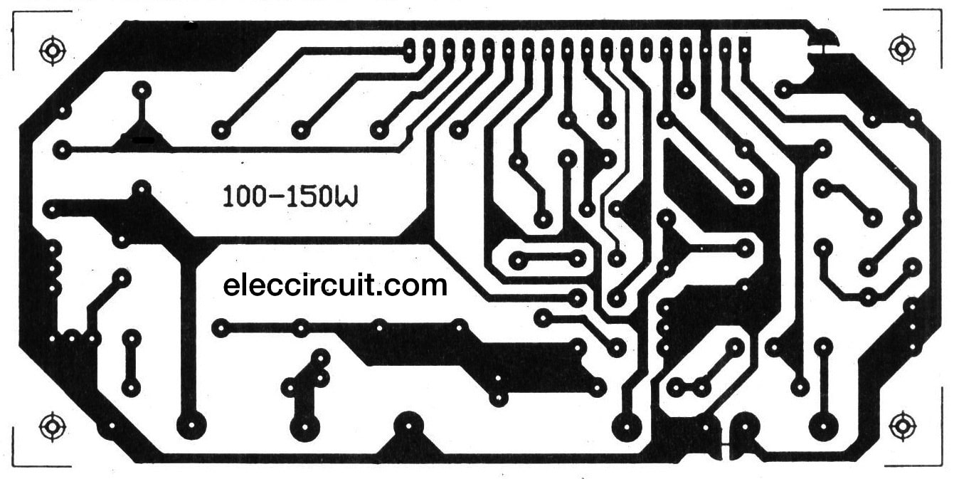
The PCB layout of STK power amplifier 150 watts
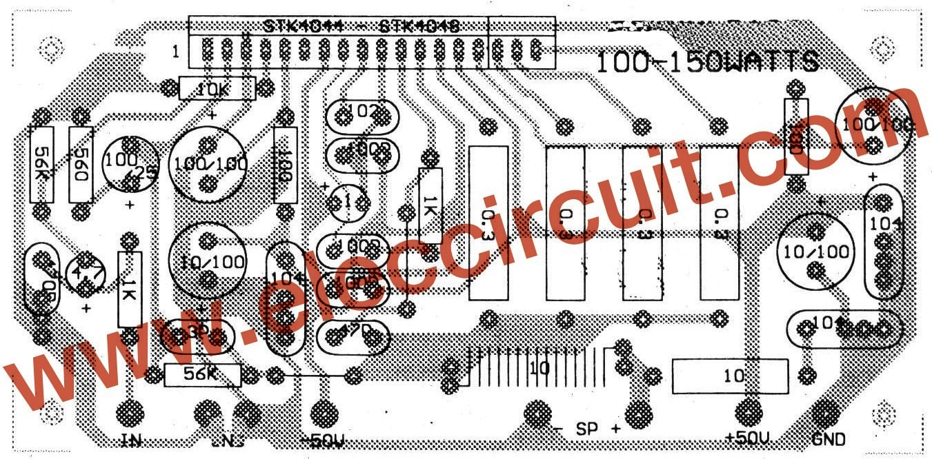
The components layout
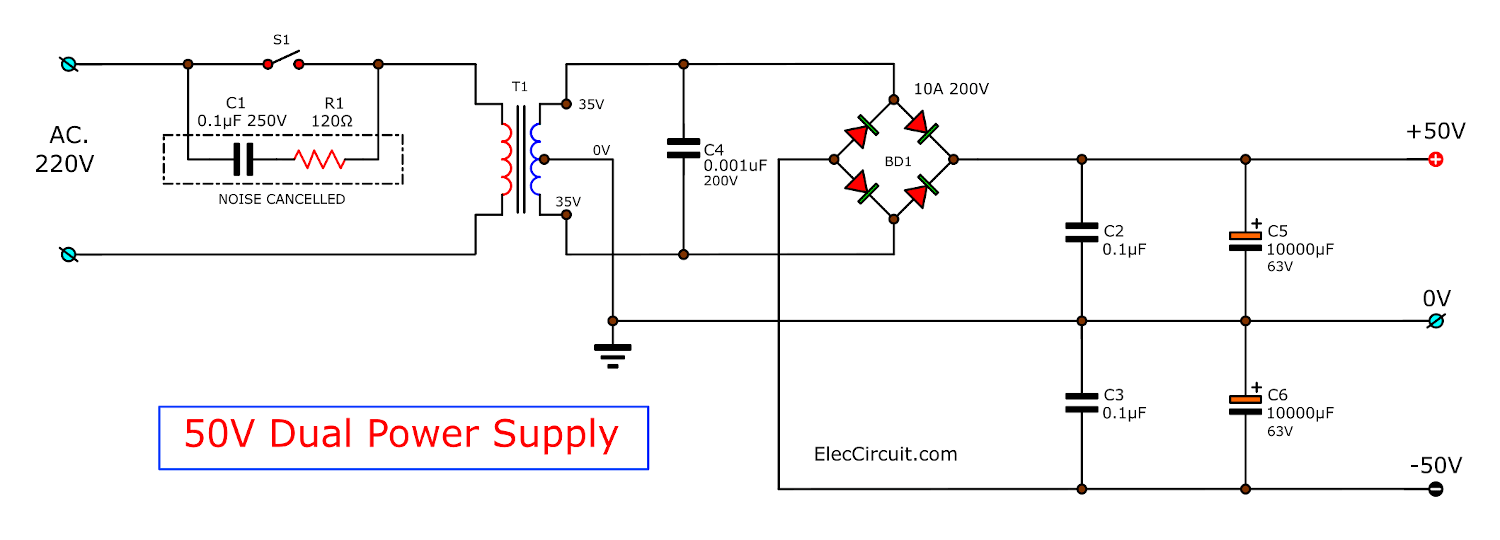
50V The power supply circuit
How it builds
Connect the device to the circuit properly, especially since the electrolytic capacitors do not reverse polarity is strictly prohibited. Because of the relatively high power circuits used in capacitors may explode easily.
When an assembly is complete, connect the power supply voltage to this circuit.
Caution! This project needs to use the speaker protection circuit. Otherwise, your speaker may be damaged.
Parts you will need
IC1(100W): STK4044XI
0.5W 1% Resistors
R1,R5: 1K
R2: 56K
R3: 560Ω
R4: 10K
R2: 100Ω
R8: 56K
R9,R14: 10Ω 1W Resistor
R10: 0.3Ω 5W Resistor
R11,R12,R13: 0.3Ω 5W Resistor
C1: 470pF 50V MKT capacitors
C2: 4.7uF 25V Electrolytic
C4,C17: 100uF 100V Electrolytic capacitors
C5* : 100pF(470pF) 50V MKT capacitors
C7: 0.001uF 50V MKT capacitors
C9* : 3-5pF 50V MKT capacitors
C10: 1uF 50V Electrolytic capacitors
C11: 0.1uF 63V MKT Capacitors
C12,C14: 10uF 100V Electrolytic Capacitors
C13,C15: 1-100 MKT
C16*: 47pF 50V MKT Capacitors
L1: Coil 22T #18AWG Dia.5mm
Note:
The device marked with * is used in cases as the growth rate decreased from 40 dB to 26 dB.
The power supply
T1: (100W) 5A Sec. 35-0-35
(120W) 5A Sec. 38-0-38
(150W) 5A Sec. 42-0-42
D1: Bridge 10A 200V
C1: 0.1uF 250V X-cap capacitors
C2: 0.01uF 100V MKT capacitors
C5,C6: 10,000uF 63V electrolytic capacitors
Recommended Others you may like them, too.
- 120 watts Super Bridge Amplifier circuit using TDA2030
- 2 CH 100W AF, using STK4231II
- 50W BCL Car Audio using TDA1562
GET UPDATE VIA EMAIL
I always try to make Electronics Learning Easy.
Related Posts

I love electronics. I have been learning about them through creating simple electronic circuits or small projects. And now I am also having my children do the same. Nevertheless, I hope you found the experiences we shared on this site useful and fulfilling.
I am very interested in this circuit (100-150W Super Hybrid Low THD Power amplifiers using STK-4048), I want to know if it is possible to buy a kit and how can I do. I live in Rome and Italy, I do not know where to turn.
thanks
Aldo Rizzo
[email protected]
I built the stk4048 amplifier on veto board and works very well.
Hi Billy
Thanks for your feedback.
I am happy hear you sound. It is power for me keep this jobs.
i hope you could indicate the technical specs of the circuit such as frequency response, distortion ( indicated already ), power supply and others.
I have 320watts Sub-Woofers(8″)-2, 20watts(8″)speakers-2, 50watts(4″)Twitters-2.
I very much interested to build a home theater. Please suggest which series STK circuit Board use for make a amplifier. please send details in my mail ID ([email protected])
—– Mahesh Bahadursha
There’s errors in this project. C5 polarity is inverted on PCB layout.Billy you can give me the layout?
Hey guys, any chance i can also get a circuit based on STK432-070.
I have an Old jvc ux-g68 would really like to use these components already on hand
Can you help
email id: [email protected]
Can I use Stk4171 ll ?
Choosing Heatsink for STK4048XI
Which size of heatsink is recommended for single STK 4048XI and for Stereo can we use one heatsink for both or using separate is better ?
Waiting for reply
In principle, there is no need to use a large heat sink. But I think it should be used in a large size first. IC has a high price And it’s very important
Que medida tiene ese pcb
Thank you that you are interested this circuit. I don’t have service to sell the PCB.
Thank you very much your excellent guide about the circuit. I will try to build it.
Hello, S.A. Ratne kumara
Thanks for your feedback.
Hello,
Your schematic of the dual 50v power supply shown using a transformer with 35v output. With the capacitors in the circuit it will output 50 volts?
Note: What do you mean by this???
The device marked with * is used in cases as the growth rate decreased from 40 dB to 26 dB.
What do you mean by this?? (if the number STK4044XI released them float the 16-18 pins.)
Appreciate your time in replying.
Thank you, Ed
Hello Apichet, I built the 150 watt audio amplifier using the STK4048XI. It works great
with a simple condenser microphone. I can hear myself loud and clear out the speaker.
When I hook up my cell phone to the input to play music it’s awlful sounding music scratchy and static. I’m just a hobbist so I don’t know why. Any help would be greatly appreciated. Thank you, Ed
Try lower your volume on cell phone output. If microphone works well there’s a good chance you’re over driving thefront end of the Amp circuit. Best of luck!
Input gain is more. That’s why. You can give a preset to decrease or adjust the input gain in between cell phone and amplifier.
stk411-550e
Saludos a todos.
¿Alguien por aquí me podría ayudar a encontrar el datasheet del IC STK407-710K?, Lo he buscado mucho, pero infructuosamente. He decidido hacer esta pregunta por todos los foros de electrónica, pero tardan en dar respuestas.
Compré es IC creyendo que sería fácil de encontrarle su datasheet, pero no lo he podido encontrar. Sin eso no puedo realizar ningún proyecto.
Agradecería que por favor alguien me ayude. Hoy soy yo quien necesita esta ayuda, mañana podría ser tú. Gracias mil.