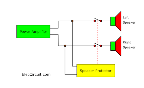
You should use a speaker protection circuit. To keep your speaker expensive! Sometimes your power amplifier may kill your speaker by accident.
These circuits are simple, small, and inexpensive. The main parts are the transistor and relay to cut off the power. You can make it in a short time with a PCB layout.
Last update: There are 2 circuits, a simple version, and adjustable load protection.
Why use the speaker protection circuit
Now a power amplifier usually builds with a direct coupling circuit. The output of the power amplifier connects to the speakers directly.
An OCL amplifier pattern uses a Dual power supply. It has three wires power, positive, negative and ground.
These types of power amplifiers are good frequency response, high power, and cheap.
But they have an important disadvantage. If they damage.
Sometimes, their output may have a positive or negative higher voltage to immediately the speakers.
With this voltage, make a coil of the speaker burn and lack eventually.
So if you do not want the speaker—the most expensive in the audio system—damaged.
You need to cut off this voltage not go out to a speaker with this circuit.
Recommended: How does an SCR work
How Speaker protection circuit Works
As shown below.
How does the speaker protection circuit prevent the speakers?
Simple speaker protection circuit
As shown in this circuit has a lot of parts for a beginner. But you are not worried. I believe you can do it.
The speaker protector circuit is good. It should have those functions.
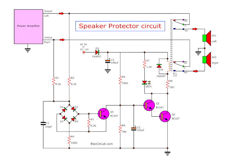
It should have these functions.
1. Soft start
When you start the OCL power amplifier circuit. If no time for delay, we will hear the noise sound “tup..” at the speaker briefly. It is a DC voltage swing. The speaker does not like it.
This circuit help this problem.—Surge protection
While beginning the power amplifier the relay does not work. So no sound on the speaker.
Why?
The first current comes to base Q2 slowly through R5-100K. It does not turn on right away. Because the current charges to C2 until full. Then Q2, Q3, and relay work normally.
Also, Diode D6 protects Q2, Q3 from the high voltage pulse. That is generated in the relay coil when the relay is switched OFF.
2. DC voltage protection
First of all, both resistors R1 and R2 reduce some lower signals from the speaker. After that, the capacitor, C1 serves to bypass this signal to the ground.
However, if the power amplifier works error. There is the DC voltage to either positive or negative comes in.
Then, this voltage flows through the bridge diode circuit(D1 through D4) immediately. They will rectifier only positive voltage to bias a base of Q1.
Now, Q1 runs.
It makes the collector voltage low down. Next, the bias voltage at the base of Q2 will also lower down.
After that, both Q2 and Q3 stop running.
Thus, no current to relay RY1 and it cuts off the signal of a power amplifier from the speaker right away. The speakers are safe from DC power.
Power supply source
You can choose one of the power sources between these 2 options.
- 9V AC—from the AC voltage source, secondary transformer.
- DC +12V—voltage from any source
It may better way you look at the circuit below.
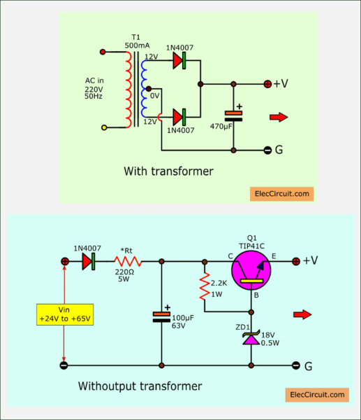
The power supply of speaker protection circuit.
You may have two options.
- With transformer—since the speaker protection requires less than 0.2A. We should use one more transformer,0.3A. Here is how easiest. It is a normal unregulated 12V supply.
- Without transformer—But if you have limited space. You cannot use a transformer. You may use some voltage amplifier power supply. Which has a voltage of 24V to 65V. We need to reduce the voltage down to 12V 0.3A. The transistor and Zener diode regulator are good for this.Note:
- You should use the TIP41C only. Because it can use with high voltage up to 100V
- If Vin is lower than 40V. Not use Rt limited current resistor. But Vin is upper than 40V. You should use Rt to limited current to a safe value.
Building and test circuit
First, get all the components ready.
The part you will need
0.25W Resistors, tolerance: 5%
R1, R2, R3: 1.8K
R4: 100Ω
R5: 100K
R6: 39K
R7: 1.2K
R4: 15Ω
Electrolytic Capacitors
C1: 100µF 10V NP(non polarized)
C2, C3: 100µF 25V
Semiconductors:
Q1,Q2: BC547, 45V 0.1A, NPN TO-92 Transistor
Q3: BC337, 45V 0.8A, PNP TO-92 Transistor
D1-D4: 1N4148, 75V 150mA Diodes
D5, D6: 1N4007, 1000V 1A Diodes
RY1: Relay DPDT 12V, 5A contact
PCB, wires, and power supply as above.
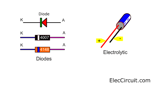
Be careful polarized components
A lot of times we have a problem with the position of the device pins. (Often, I accidentally switched its legs) It causes the circuit work error. See below again!
Relay runs but No light! Check LED
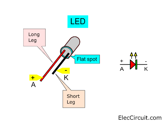
Check Diodes and all Electrolytic capacitor, too. Sometime, relay does not work because we put it switches. Even the transistor is over heat, too.
Secondly, make a PCB. If you want fast and cheap to build this circuit. You may use a Perforated universal PCB. But some people might not like it. You want to make a normal PCB, of course, it is better. But it may be time-consuming and costly. Look at the PCB layout below.
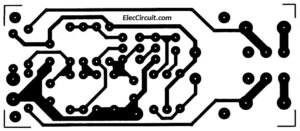
PCB layout
Then, assemble all parts on the PCB as the components layout below.
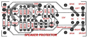
Components layout
Next, Check the correct devices, and soldering is done at every point.
How to use
- Connect the ground wire from the amplifier to the ground of the protection speaker.
- Then, connect the signal output from the amplifier to the speakers. We connected it to the IN of the protection speaker to both the left and right.
- Next, connect the OUT signal from the speaker to the positive terminal of the protection speaker.
Testing the functionality of the circuit
- Connect a power supply circuit. You will see the LED grow up, and hear a click at the relay. It is working.
- Experiments DC voltage protection, connect DC voltage at the IN of any speakers, the LED will extinguish along with the relay will stop immediately.
If you want a more efficient circuit. Continue to look at the second circuit.
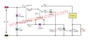
Speaker Protector circuit with adjustable sensitive
This circuit has more components, 6 transistors. Important, we can adjust the sensitivity. Because various power amplifier has output power are different, and more…
Look at above. It is the full circuit diagram. If you are beginner. It will look complicated. Do not worry. I will try to explain it for you easily.
4 qualities that a good circuit should have
Soft start
Eliminate unwanted sounds at the start. This circuit has the time delay mode in 2 s.
It means in first we turn on the amplifier. The speaker will be quiet for about 2 seconds.
Look at the circuit above, C2 and R3 are simple delay circuit. I will redraw circuit to basic block diagram.
Download This
All full-size images of this post are in this Ebook: Elec Circuit vol. 2 below. Please support me. 🙂
If it does not follow this. Show that a failure occurred. Make sure to found before it is available.
Testing this circuit on Multisim 13.0
If this circuit is too many hard. You do not need to use it.
Sometimes you may like the circuit below.
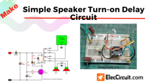
Simple Delay Speakers
GET UPDATE VIA EMAIL
I always try to make Electronics Learning Easy.
Related Posts


I love electronics. I have been learning about them through creating simple electronic circuits or small projects. And now I am also having my children do the same. Nevertheless, I hope you found the experiences we shared on this site useful and fulfilling.
This website contents is very old. However is a very helpful to my students.
Thank you.
Thanks for your feedback.
This circuit is very simple to make and very useful.
Thank you for help us.
Thank you for supporting I and my dad. I and my dad will concentrate continuously on making articles. 🙂
very nice and simple circuit
I like simple circuits. Because I’m just a beginner, my dad teaches me every day, but it’s hard for me. But I’ll keep trying. 🙂
For anyone currently in such a predicament they are in luck.
To speed up this process we are going to stage an ARP replay attack.
All sorts of handsets in the UK souk is available with myriad deals like the contract and the pay as you
go from operators like Vodafone, Orange, O2 and
T-Mobile.
so if we need the same circuit for 5.2 Audio System means , how we can modify the circuit , And y we r connecting the speakers in serious , output line of the speaker should be in parallel to each other …
Sureshkanna: you missed the ground that’s between the speakers, i.e Parallel in the end.
for 5.1 just add 5.2K resistor in series as currently, and add how much output you want.
I run simulations on it seems to be working fine, will try practically, Going to use it for DIY 5.1 Amplifier.
Hi. Will this circit work with amp which have +-56V at output transistors?
Than you for the circuit. u tested this circuit perfectly working for dual DC components positive dc component and negative dc component. i want to add 5 sec delay to this circuit. Please suggest.
Hi L Srinivasa Murthy A,
Thank you too, for visiting. I am so happy your project works. You can adjust delay time with C2-100uF. You may try to increase capacitance up to 220uF take longer time. I hope it will work well.
What does AC9V, DC12 mean on the first schematic?
Would the above mean I can use either a 9VAC voltage or a 12VDC voltage.
We use the power supply of this circuit in two ways of choosing.
9V AC—from the AC voltage source, secondary transformer.
DC +12V— voltage from any source
Will the circuit work with a bridged amplifier since no speaker ground is present?
In the event it will operate properly, how would the speaker output of the protector be connected.
I built the circuit and it is working excellent on a normal speaker output that uses one side as ground but not sure if it will operate properly with a bridged output.
why is D6 diode parallel to the relay used? what is the reason?
Hi efrem,
Diode D6 protects Q2, Q3 Please read more in text: https://www.eleccircuit.com/speaker-protection-circuit/#How_it_Works
What if instead of using this circuit, you simply add a capacitor between amp and speaker to avoid DC Coupling. Wouldn’t that simplify the circuit to solve the same problem or, am I wrong ?
By the way, I would like to know the function of resistors R3, R4, R6, R7, R8.
Hello, Víctor
Thanks for visiting my site.
Apologize, I do not quite understand your question.
The function of those resistors on first circuit are:
R4 reduces the current flowing through the Bridge Diodes (D1 to D4).
R3 optimizes the bias voltage of Q1.
R6 and C2 help determine the delay in the initial stage (soft start) of the amplifier turn-on.
R7 is a limiting current resistor for LED1.
Have a good day.
Apichet
Is it possible to use this circuit with a subwoofer amplifier like this from Amazon–DC 12V-15V 25W~30W Subwoofer Amplifier Board Mini HiFi Class D Mono Channel Digital Audio Power Amplifier Super Bass Amp Module for PC Computer Desktop Speaker, Car Audio Speaker
Brand: QINIZX
ASIN # B09Y5C1BC7
Thanks
Richard
Will it work with Class D mono amplifier?