This is an electronic Stethoscope circuit. Usually, the stethoscope is a medical device that listens to the heartbeat.
It is very useful. Do you believe it? We can try to create it. With a simple electronic circuit.

Which we can make it with principle working looks like a preamplifier circuit. So, easy to make.
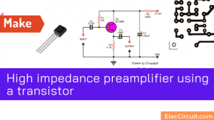
Learn also: High impedance preamplifier using a transistor
How it works
See the block diagram below.
We use piezo speakers as a microphone. This is transducer can power output signal up to 100mV at the low-frequency response. This signal is very tiny.
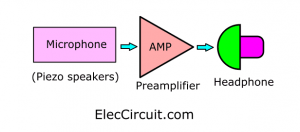
So, we need to use a high-impedance input impedance preamplifier to increase the signal up. To drive a headphone output.
Recommended: Hi-Fi headphone Amplifier circuit
What is more? See the simple circuit below.
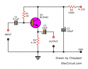
This is simple high impedance preamplifier using only one transistor. Is it easy? Yes. We can modify just a little to better. See below.
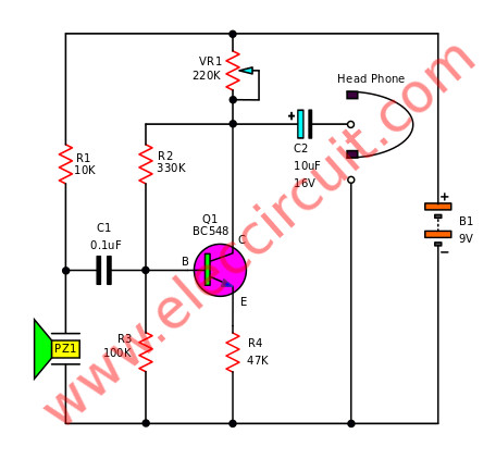
Electronic Stethoscope circuit
Read Also:
- 4 types of Preamplifier circuits using Transistors
- High impedance small amplifier circuits
- Try simple FET Preamplifier circuit (Very high impedance)
Here is step-by-step a process.
The piezo speaker(PZ1) will detect the heartbeats. Then, the signal comes to a signal amplifier that consists of Q1, in combination with R1-R4, VR1, and C1.
Some called it that a common-emitter amplifier. The input and output signals both share a connection to the emitter.
It can output response with low frequencies. So the output is connected to the headset with low impedance.
To be able to listen to the heartbeat. The VR1 will act as a volume adjuster to loud or low.
We can use the Darlington transistor to increase the input impedance of the amplifier.
Want more brilliant ideas? Here’s how to get them through electronic circuits.
Parts will you need
Resistors 0.25W, tolerance: 5%
R1: 10K
R2: 330K
R3: 100K
R4: 47K
VR1: 220K Linear Potentiometer
Capacitors
C2: 10µF 25V, Electrolytic Capacitors
C1: 0.1uF 50V, Ceramic Capacitors
Semiconductor and others
Q1: BC548, BC547, BC549, 45V 100mA NPN Transistor
PZ1: piezo speaker
Headphone
B1: 9 volts battery
Universal PCB
Check out these related Circuits, too:
- Low voltage preamplifier circuit with tone control
- Acoustic guitar pickup circuit using TL071
- Hi-Fi transistor headphone amplifiers

I love electronics. I have been learning about them through creating simple electronic circuits or small projects. And now I am also having my children do the same. Nevertheless, I hope you found the experiences we shared on this site useful and fulfilling.
simple circuit, keep post!