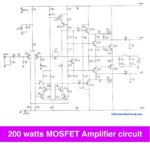
If You want to circuits amplifiers for bass guitar, or for using in every situation such as both listen to in the house, outside the house or outdoors. This circuit is answer that you is looking for. It is guitar amplifier circuit diagram with pcb layout. It is wisely designed with power output at 200 watt in super bridge model so help to you have a high quality circuit in cheap.
The characteristics of the circuit as shown in figure 1. When we carefully consider found that amplifier circuit consists of two sets are:
– The first circuit set consists of many transistors Q1(MPSA06), Q2(MPSA06), Q3(MPSA56), Q4(BC182), Q5(BC182) ,Q6(BC212), Q11(MJ3001) and Q12(MJ2501)
– The series 2 circuits consisting of Q7(MPSA06), Q8(MPSA06), Q9(MPSA06), Q10(BC182), Q13(MJ3001), Q14(MJ2501).
Both of these circuits has pattern is very similar, but slightly different, is the series 2 circuits cut off the protection circuit of section output transistor to go out. And we enter the input signal to input of first circuit only.
-But the differential input of the series 2 circuit is connected to ground. While the output of first circuit is entered to R28 to inverting input of Q8 makes output of second circuit is 180o out-of-phase automatically.
– With this setting wisely so do not need to connect bridge adapter circuit that difficult and too expensive.
How it works
-The signal is entered the input jack and SEND jack and RETURN to C1 to the differential amplifier Q1.
– the signal is amplified out to collector and pass through R3 to base of transistor driver circuit of Q3.
– The output at collector pin Q3 will pass two R7,R16 to drive the power transistors Q11,Q12.
– The Q5 is setting bias current of transistors output in reasonable range.
– Two Q4,Q5 are protection working of the power transistors not has too high circuit. Which may occur of the short circuit by output. We have both resistor R12,R13 are output signal detector. If the current exceeds the value set will be a high enough voltage across to make Q4, Q6 work.
– The voltage that enter to base of Q11,Q12 will be short circuit by Q4,Q6 as above, Until the output current is reduced and lower in a satisfactory security.

– The output signal is entered pass through a coil L1 to loudspeaker, the another to inverting input of the second pass to R20 as above in begin At the same time the other signal will be entered R9 into inverting Q2.
– Growth rate of the circuit is determined by the value of R9 and R8, C5.
– The another still to work as same the first circuit so I would like to explain to you every time.
The power supply
– The voltage that use in the circuit get from this power supply that composite of the transformer T1 is reducer AC volt 220V lower to 20V – 0 – 20V.
– The transformer in use, If you have mono amplifier so you should have the ability to Supply Current not lower than 4 amp and do not lower than 8 amp in stereo amplifier system.
– Four diode D1-D4 are changer the AC to DCV , Capacitor 4700 microfarad 2 pcs, to parallel circuit filters. Which you may choose capacitor 1,000uF 35V to replace them.
– The output voltage of this power supply equal to the positive and negative 28 volt at 4 amp.
– The output power will be under 200 watt at load 4 ohm.
The parts
Q1,Q2,Q7,Q8_____________MPSA06
Q3,Q9___________________MPSA56
Q4,Q5,Q10_______________BC182
Q6______________________BC212
Q11,Q13_________________MJ3001
Q12,Q14_________________MJ2501
R1,R9,R23,R31___________10K_______1/2W resistors
R2,R24__________________2.2K______1/2W resistors
R3,R4,R15,R26,R27,R34_______10 ohm____ 1/2W resistors
R6,R16__________________270 ohm___1/2W resistors
R7,R25__________________39K_______1/2W resistors
R8______________________220 ohm___1/2W resistor
R10_____________________3.3K______1/2W resistor
R5,R11,R17,R33__________1.5K_______1/2W resistors
R12,R13,R29,R30_________0.39 ohm ___ 2W resistors
R14,R35_________________4.7K_______1/2W resistors
R18,R36_________________3.9K_______1/2W resistors
R19,R20,R37,R38_________390 ohm____1/2W resistors
R21,R22_________________10 ohm ____1W resistors
R28_____________________100K______1/2W resistors
R32_____________________2.7K_______1/2W resistors
C1______________________0.68uF 63V___Polyester Capacitor
C2,C3,C9________________ 220pF 63V___ Polyester Capacitor
C4,C6,C10,C16____________0.047uF 63V_ Polyester Capacitor
C8_______________________0.22uF 63V__ Polyester Capacitor
C5,C7,C1_________________100uF 63V___ Electrolytic Capacitors
D1,D2____________________Zener Diode 9V 0.5W
D3,D4____________________1N4148 75V 150mA Diodes
L1______________________10uH Inductance

How to creation
– All equipment except the diode bridge can be placed onto PCB as show in Figure 2.
– Why we do not install the diode bridge on the PCB, It’s so convenience to install diode into the chassis. or heat sink there.
– Soldering equipment follows the circuit in the correct completed. The devoiced terminal such as : capacitor and diode to be careful in a terminal. Otherwise may result in damage to the circuit or not.
– In addition, care must be taken for each transistor. Particular transistor of the same size. Do not connect the switch to absolute numbers. For this circuit to watch out Another one, is a little like the pin transistor MPSA and BC-emitter and collector to position the legs contradictory.
– Another is to heat the soldering iron to solder to close tightly enough. Transportation equipment with PCB. Feature points to be soldered to a smooth flat or pitched ball is held.
Caution! This project needs to use the speaker protection circuit. Otherwise, your speaker may be damaged.
Testing project before the real use.
To experimental power supply to the circuit, then measure the voltage at the output of the amplifier with two speakers, it must be zero, so will be connect to speakers. If the voltage is not zero. You need to find them. Then, so speaker connections and input signals, respectively, shall completed ready will used as needed.
Related Posts
I love electronic circuit. I will collect a lot circuit electronic for teach my son and are useful for everyone.
I WANT TO BUY PCB AND ALLIED COMPONENTS OF THE DESIRED CIRCUIT. PLZ LET ME KNOW THE PROCEDURE, HOW TO BUY?
It is able to use silicon power transistors?
It is able to use silicon power transistors?
Yes,ahh but a need an answer too..
Hello!
I am interested in making this amplifier but I have a doubt about a component reference.
In the diagram the values of R7 and R25 correspond to 39 ohms, but the list of components value is 39K.
What is the correct value?
Thank you!
Hello, I’m very interested in this project, but I would like to know which size of board should I print the PCB into?? Thanks!!
Your mode of explaining the whole thing in this piece of writing is genuinely nice,
all be able to without difficulty be aware of it, Thanks a lot.
The circuit is correct R7 & R25 should be 39 ohms (39R or 39E) not k ohms
Hi. I want this for a bass guitar, but I don’t see tone controls, like bass, mid and high. I need to be able to control the amount of bass and trebble on the sound. Please include it-
Hi,Collen
Now I do not have a circuit that you want.
Further, if I had such a circuit. Will let you know via e-mail
or Please visit us constantly.
Thanks for your feedback.
Thank you for your speedy reply. I’ll keep visiting-
Hi. I found that you do have a pre-amplier circuit in your website at
https://www.eleccircuit.com/three-circuits-of-preamp-tone-controls-by-ne5532/
Could it work with this guitar amp as in, the guitar as the input into the pre-amp and the output of the pre-amp into the actual amplifier. I have been doing some reading and realised that basic amplifier circuits don’t have tone controls, its done on the pre-amp-
Thank you very much
Can someone has the PCB pattern (footprint) for this scheme in vector format or in a special file?
please send me an email
The power supply stated is 28v centre tapped what variation on the supply Voltage as I have a 28v Centre Tapped Transformer and it will push the voltage up around 35-38 Volts. Could this be used. Thank You
what if I am using 30V 10A center tap transformer and instead of MJXXXX series power transistor I use TIP 142 and TIP 147 transistors, would this circuit function?
Hello
Can I order PCBs alone.
Hi leo,
I’m very thankful for your interest in the project. Unfortunately, we do not have PCB service.
I try to diy this guitar amplifier but the pcb have no exact size.please …