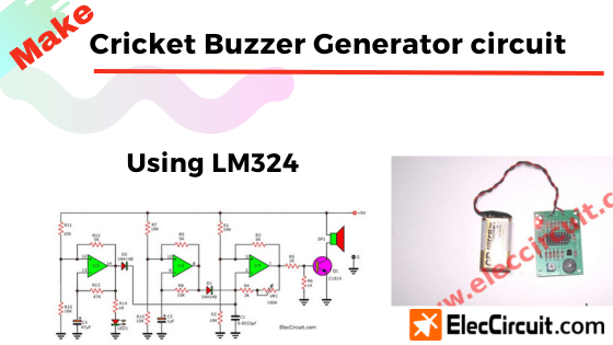
Are you bored with the ordinary sounds of a buzzer? This is a cricket sound generator circuit. Which it is another Sound effects generator using LM324 op-amp and emits by a buzzer. And they have sound similarly the crickets are singing a couple we’ve ever heard.
In-circuit, we don’t use any microcontroller ICs so you can build easily them and also cheaper.
Technical information
- Use a power supply of 9 VDC.
- Maximum consumption current about 30 mA
- PCB size : 2.25 x 1.57 inch.
- With trimmer to adjust the tone.
- PCB dimensions: 2.25 x 1.57 inches.
How the cricket sound circuit works
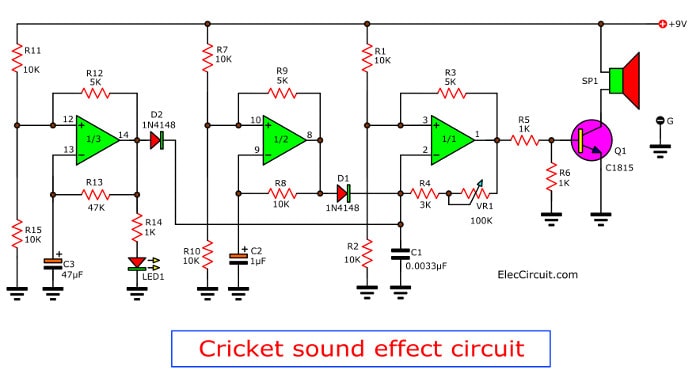
As Figure 1 is this cricket sound generator circuit use LM324 Op-Amp IC. It has Op-amps within 4 units. But this circuit use only three op-amps, another floating out. The three op-amps will be used as the frequency generator circuit.
IC1/1 generated Tone Generator at a frequency of about 1400Hz to 15kHz. This frequency depends on VR1, R4, and C1. Which acts set the cricket tone.
IC1 / 2 generates a frequency of about 50Hz. This frequency depends on R8 and C2. Which it serves to control IC1 / 1. To give a voice tone similar to the sound of crickets.
Related: 6 sound effect generator circuit using MM5837
IC1 / 3 generates a frequency of about 2.2Hz. This frequency depends on R13 and C3. This frequency to control the IC1 / 1. To sound frequencies for a cricket singing then stop.
Therefore, the sound of crickets is a tone generator circuit 3 sets. Which sends out pin 1 of IC1 / 1 R5 to pass on a TR1 amplifier to the speaker on.
Building the cricket sound circuit
This project you can assemble all parts on the perforated board or universal PCB board. As Figure 2 is the components layout and wiring of this project. And as Figure 3 is a project that I assembled on PCB and success to the next test.

Figure 2 the components layout and wiring
Check out these related articles, too:
- UM3561 Sound generator circuits
- 555 Sound effect generator circuit
- Sound effect generator using CD4040 CMOS
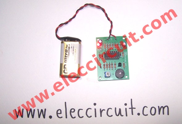
Figure 3 is the complete projects on PCB.
Recommend: Electronic drum circuit (simple)
Testing
To apply a 9 volts battery to point “9V” LED lights are the bright start – off at rhythmic. The range of LED lights and can be noisy as well. To adjust to the sounds of crickets, high or low, it can be adjusted to VR100K.
As the video below is testing this project.
The part list
0.25W Resistors, tolerance: 5%
R1, R2, R7, R8, R10, R11, R15: 10K
R3, R9, R12: 5K
R4: 3K
R5, R6, R14: 1K
R13: 47K
VR1_100K (104 code) TRIMMER POTENTIOMETER
CERAMIC CAPACITOR
C1: 0.0033uF (on 332 code)
ELECTROLYTIC CAPACITORS
C2: 1uF 50V
C3: 4.7uF 50V
TRANSISTORs
TR1: 2SC458 or 2SC828, 2SC1815, 2SC945
DIODES
D1, D2_1N4148___75V 150mA Diodes
IC
IC1_LM324 Quad/ 1MHz/ Operational Amplifiers for Commercial/ Industrial/ and Military Applications
Buy this IC at Amazon.com here (affiliated link)
B1: 9-volt battery Or 9V power supply circuit
Also, here are a couple of related posts you should read, too:

I love electronics. I have been learning about them through creating simple electronic circuits or small projects. And now I am also having my children do the same. Nevertheless, I hope you found the experiences we shared on this site useful and fulfilling.


sehr schön!
danke.
viele grüße…..
thanks alot for your efforts u share with us
Hi,walter
Thanks for your feedback.
Hi,walusimbi frank.
Thanks for your feedback.
Great web site. A lot of helpful info here.
I’m sending it to a few pals ans also sharing in delicious.
And certainly, thanks for your sweat!
Hi Jet-Lube,
Thanks for your feedback.
hi all,
i tried this circuit on breadboard but its not giving the desired output instead giving a continuous beep….can you guys please help me…thank you in advance