I love to collect a lot of circuits. A filter circuit is important in Electronics. I will show you many ideas of noise hum, high-low frequency, and more. Some will smile it so easily and without a power supply. These are small circuits, so easy to apply, and try into your works.
There are seven ideas for you.
Hum Filter circuit using electronic coil
There are many ways to filter the humming noise from the AC line (50 Hz) or audio signal away. This is a Hum Filter circuit using an electronic coil. Using a frequency filter is a simple way that includes RLC as the electronic coil.
See figure below, the specific frequencies filter.
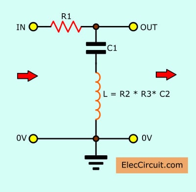
We thoroughly consider filtering frequencies at 50 Hz away. We need to use a value of Q equal to 10. And, the inductance is almost 150 uH. Which is difficult and larger.
It is easy when using an electronic coil in Fig below instead.
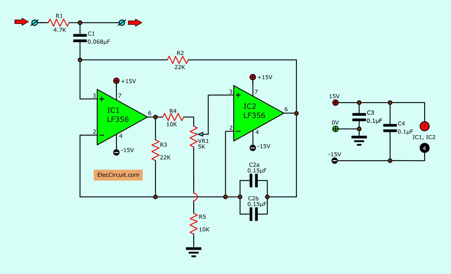
This circuit operates by two op-amps and R2-R5, C2, and P1 Including the virtual coils. Which the inductance will take place at pin 3 of IC1 to the ground. This inductance depends on the value of R2, R3, and C2 (as the formula: L = R2 x R3 x C2), and can also adjust potentiometer-P1.
If this circuit is adjusted correctly, The attenuation of frequency 50 Hz, will be 45 to 50 dB. This is enough to be used for attenuation hum sound for the harmonic distortion meter. Or Hum filter for audio signals from the TV.
Parts you will need.
IC1,IC2: LF356A
C1: 68n or 0.068uF 50V, Ceramic capacitor
C2a, C2b: 150n or 0.1uF 50V, Ceramic capacitor
C3,C4: 100n or 0.1uF 50V, Ceramic capacitor
R1: 4.7K 0.25W Resistors tolerance: 5%
R2,R3: 22K 0.25W Resistors tolerance: 5%
R4,R5: 10K 0.25W Resistors tolerance: 5%
P1: 5K potentiometer
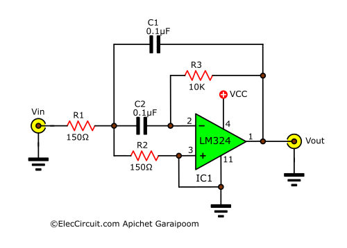
1kHz bandpass filter circuit using LM324
When you want bandpass Filter circuit Frequency circuit 1KHz size in model easiness. I begs for to advise this circuit , because it uses , IC LM324 OP-amp highly popular the one number. By this circuit Filter frequency 1kHZ especial can change only. By we can can fix with R1,C1,C2 , and R2. Lay vacate other see in circuit picture.or not view other images in Filter circuits using op amp
Note : This circuit worked great as video below please watch.
Thanks
Band rejection filter circuit using TL071
The band rejection filter circuit is not wide filter that can denial the frequency up to 60dB by we used the TL071 single chip op-amp it is very low distortion and work good at output to maximum to 100kHz or the range 1Hz to 20kHz. In the circuit we defined three resistors R1,R2,R3 are like value to 100K, and then two capacitors C1,C2 are equal to 330pF, For will reject the frequency at 50Hz.
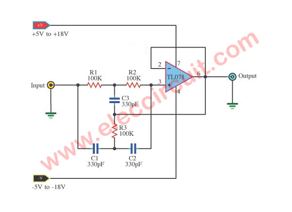
By we can select the parts with the formula is F = 2×3.14xRC , And to get rejection well than 40dB if we should the resistor matched to 0.1% and capacitor to 1%.
The circuit is the right narrow filter for well audio system, we hope you enjoy with this circuit ideas.
High Q notch filter
In the circuit Figure 1 shown, Twin-T network connections with LM102 in form of High Q notch filter.
Usually, the junction of R3 and C3 to ground, is bootstrapped to the output of the follower.
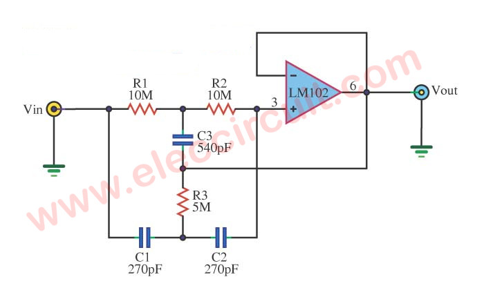
High Q notch filter
Because it has a very low impedance,neither the depth nor the frequency of the notch change.
However, Q increases in proportion to the amount of the input feedback signal to the R3 and C3,
the response of the twin-T and the response to the follower input.
60Hz Notch Filter by LM741
In the Figure 2 sometimes when want to decrease especial frequency noise that want only. This circuit can help you , it does will not let 60HZ frequencies s can change. Then decrease the noise. By use the integrated circuit , 741 numbers highly popular , economize and don’t seek buy easy with , if , friends , want to filter especial which frequency the one frequency. As a result change the value RC see the detail has added in the circuit.
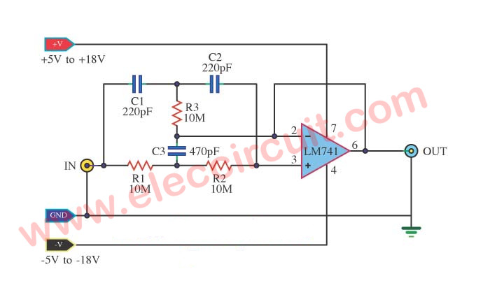
60Hz Notch Filter by LM741
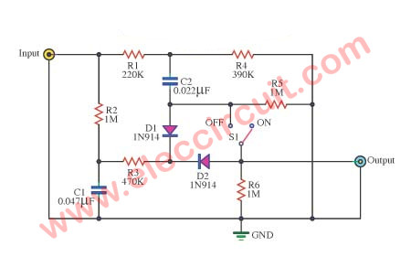
The Filter circuit for the Scratch and Rumble Noise
If friends get into trouble about the noise. Try out this circuit before, may like. It is Filter the Scratch and Rumble Noise Circuit. That makes a friend feels annoyed very the character of the circuit filters this frequency , use , Resistor , and , Capacitors , or , RC Filter that often call that Passive Filter Circuit.
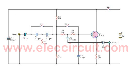
By have Switch choose filter the noise. By SW1 for Rumble noise Filter and the SW2 for Scratch noise filter. Make the noise that change this circuit goes to are left a little for power supply Source should use battery 9V. Because will decrease the noise from power supply , give with this circuit there.
Low pass filter circuit 10KHz using uA741
This be the circuit filters 10KHz low size frequencies s use IC op-amp the highly popular number uA741. By this circuit convenients for to apply to input and output of the circuit changes analog signal be digital or the circuit changes digital signal be digital. In sound system of digital for synthetic the voice or music give for make wave form output the smooth. And press the noise that happen at output. When small-sized signal was managed with decrypt linear the size is 8 bit.
Low Pass Active Filter by LM741
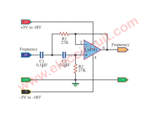
When you want to filter low frequency gives can change only. I thinks the Low Pass Active Filter circuit help you. Because of it uses IC LM741,then usable easy follow circuit image. We can fix the frequency is cut off get, by equipment value R1=R2 = R , and C1=C2=C When fix give 50Hz frequencies low only that can change. Values Show be valuable about 0dB = 50Hz , -3dB = 250Hz , -50dB = 10kHz
Then will see tall frequency 50Hz more cut give until less is finished. This circuit should use dual power supply positive,negative,GND +/- 5V to 18V in order to get a signal that is appropriate most.

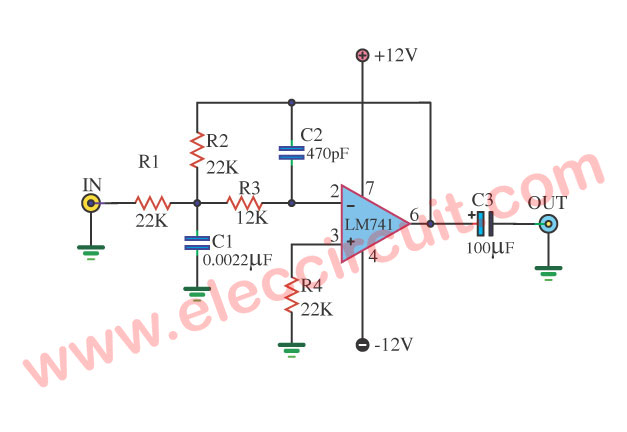
Simple High Pass Filter using IC 741
This be Simple high pass Filter perform filter especial tall frequency can change only. By use IC 741 , be the integrated circuit op-amp very the circuit helps to are high-frequency Filter model to be simple. By from the circuit will let 750 HZ frequencies s go up change more well, 60HZ frequencies are or lower. By friends can change the value RC for filter the frequency that can want, it allows this circuit has a lot performance and has cut off frequency precise.
Despite the possibility of multi-circuit filter,with different levels of growth and differentiation of a roll back in the op-amp IC. But this circuit can reduce the frequency cut off, so successful, the device configuration, R1 = R2, C1 = C2. which can see the detail has followed circuit picture.
Active High Pass Filter Circuit using LM741
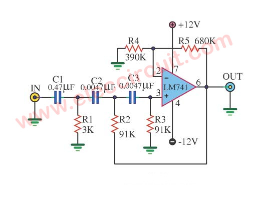
This is active high pass filter circuit for 327Hz frequency using LM741 or LM741 circuits.
It will use to build Harmonic at 3 of 130.81 frequency have the value at least. More than the frequency Fundamental 30 dB, for output be sawtooth waveform for use in sound of music way system Electronic design will use the circuit filters three rank frequency. By having 3 dB you slopes can use Op-amp IC number LM741 or number LF351, it will meet the frequency well.
Cheapest video signal cleaner circuit
Here is the simple low noise filter circuit for any FSK signals or video signal cleaner circuit that weak and has noise. This use few parts so easy and cheap.
The schematic of this project
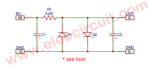
As above is the schematic diagram. This circuit includes the low filter circuit through R1 and C2, the frequency cut off at 1,600 Hz.
In the FSK system, logic “0” instead of with the frequency of 1,200 Hz. Thus, this filter will reduce the roughness of the edge signal as two waveforms (A) and (B). watch on the oscilloscope.
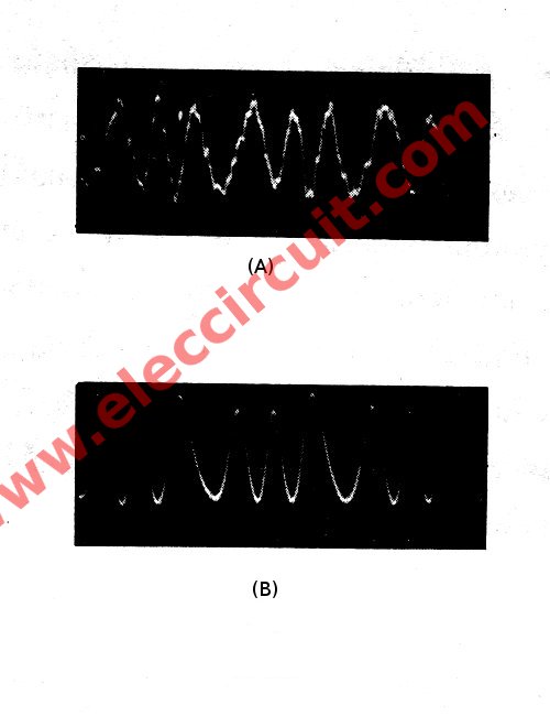
The signal is cleaned well
Both diode D1 and D2 are used to limit the maximum input signal to lower than +/- 600 mV.
The parts you will need.
D1-D2: 1N4148, 75V 150mA Diodes
R1: 5.6K, 0.25W Resistors tolerance: 5%
C1: 0.0082uF 50V, Ceramic Capacitors
C2: 0.018uF 50V, Ceramic Capacitors
Note:
You can use all signals that lower voltage than 0.6v.
Example. TV, Audio signal.
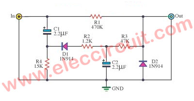
Noise limiter signal
Interference from ignition noise pulse of the engine, it can cause various problems associated with radio communication equipment installed in the car.This circuit improves signal to noise ratio (S / N-ratio) was better, To connected between the output of the detector circuit with the audio input (if high impedance) or region of the impedance between the high dance audio section.
The diode D1 and diode D2 is there any way to direct the resistance is quite low and very high back resistance.
This circuit for the rf receiver has low bandwidth still 2kHz also 3 kHz
Simple non linear low pass filter
This is a simple non-linear low pass frequency filter circuit on passive model. We use passive components without transistors and any ICs. So is an easy circuit. and It is small size and easy to made for do not used the external power supply, but refuses a lot of noise ripples and needs to an input voltage is stable. and lower amplitude.
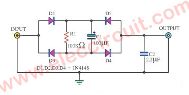
The circuit will work best when the signal level is importantly higher than the constant ripple level. And
The circuit has specifically related to two peak-detecting sample-and-hold circuits in tandem with a voltage average.
There are parts in the figure below (a few parts):
D1-D4=1N4148, C1=100uF electrolytic ,C2 – 2.2uF ceramic, R1 -100K
I hope this circuit are a little ideas your, to a big project next time.
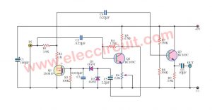
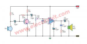
Simple compressor with 1N914
This simple compressor circuit is suitable for use in a recorder tape from the speaker terminals of the receiver. This input can be changed from 200 mV to 6V. The output will remain at close to 5 mV. The attack time of the circuit for about 3 ms and release time of approximately 100 milliseconds, for the diodes in the circuit should be the type of high back resistance, such as number 1N914.

I love electronics. I have been learning about them through creating simple electronic circuits or small projects. And now I am also having my children do the same. Nevertheless, I hope you found the experiences we shared on this site useful and fulfilling.

Thanks.
Hi Salim Khan,
Thanks for your feedback.
Frohe Weihnachten an alle Bastler
Hi walter,
Vielen Dank für Ihr Feedback. Frohe Weihnachten und ein glückliches neues Jahr.
I like to buy printed circuit board single/ double layer as per my choice of your various circuits. Kindly let me know the cost of PCB as per sq cm., if is it possible the delivery would be taken by courier.
Nice circuits but the grammar makes it difficult to read.
Hello William Gates,
Thanks for your feedback. Yes, My English is not very well. I am improving it. Please tell me how to get better English for reading clearly and being easy to read. Sometimes you may help me.
Thanks again.
Apichet