Imagine you are playing an instrument, a guitar. Sometimes you want a strange sound from a normal. Use these ideas of fuzz box circuits and fader controller.
You may change the mood of your guitar playing. Let’s change the boring time with your own creations.

I am going to show you 3 circuits below:
1# Simple Guitar fuzz box circuit
If you have little time and are learning electronics about op-amp circuits, this is a good option.
How this circuit works
See in the circuit below. This circuit we use IC-741 op-amp. Normally use a Dual power supply(+/- ground). But, this circuit uses a single power supply to easy to operate.

Figure 1 is a schematic of this project.
The input signal is fed to C1 to pin 3 of IC1. Which this has gain equals the value of (VR1+R2+R3)/R2. And the gain change from 6 to 92, depending on the adjusting VR1.
However, the output voltage is less than 600mV. Since connecting both diode D1-D2 in the feedback circuit. And connecting a signal attenuation circuit by R6, R7.
Therefore, the signal output from the IC was down to only 150mV.
Recommended: Learning electronics for beginners
How to build
In the building circuit, we can use a perforated board or a normal PCB as Figure 2.
It is an actual-size of the single-sided copper PCB layout.

Figure 2 the copper layout
And assemble parts on PCB as Figure 3
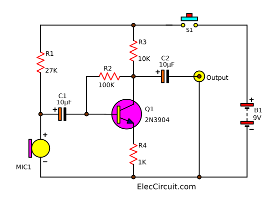
Figure 3 the component layout
For switch-S1 is available to choose. Will continue to play with the direct signal or the signal through the circuit.
Parts you will need
IC1: LM741, single op-amp or LF351 (Better low noise FET op-amp).
D1, D2: 1N4148
R1: 100K Resistors 0.25W
R2: 1.2K Resistors 0.25W
R3, R4, R5: 10K Resistors 0.25W
R6: 3.3K Resistors 0.25W
R7: 1K Resistors 0.25W
C1, C3: 0.1uF(104) 50V Ceramic or Mylar capacitors
C2: 10uF 16V or 10/16V Electrolytic capacitors
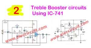
Read next: Treble Booster circuit
Read others: I want you are happy to learn electronics. See other sites that make you grow up.
2# Fuzz pedal schematic
This is Fuzz audio converter circuit. It uses two diodes as a feedback circuit of OP-AMP IC, LM324.
Also, this can make a musical sound that has unusual characteristics. And it will limit output voltage, give a hand net between 0.7Vp-p waves square signal.
Which this result will proportionate big compose harmonic be the odd number. It resembles the sound of a donkey.

The VR1-resistor is used to adjust the depth of fuzzy audio. It will use fine the level top waves slitting goes up. And the VR2-resistor adjusts the intensity of the output signal.
Recommended: Sound effect generator circuit using CD4040
What is more? See other fuzz box circuit ideas.
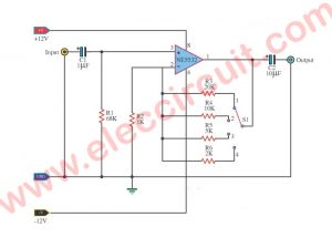
3# Signal Automatic Fader using LF351
This is a Control signal Automatic Fader circuit. It helps to adjust the decorate or control sound signal highly or low as you want.
In the model the automatic convenient for the system electricity guitar, Audio sound operation.
Look in the circuit below. It uses the FET as a preamplifier. Then, it has the high-frequency op-amp, in low noise FET model, LF351.

Which it has disturbed lower. The S1 for adjusting the pitch High or Low get, and have decorates the pitch done to a turn VR1, VR2.
You can the detail adds in the circuit.
Check out these related articles, too:
- Passive tone control circuit
- 3 Tone control circuits using op-amp NE5532
- Bass guitar super bridge amplifier 200 watts
GET UPDATE VIA EMAIL
I always try to make Electronics Learning Easy.
Related Posts

I love electronics. I have been learning about them through creating simple electronic circuits or small projects. And now I am also having my children do the same. Nevertheless, I hope you found the experiences we shared on this site useful and fulfilling.
Does IC-741 stand for LM741?
That LM324 circuit has the + non-inverting and – inverting inputs reversed, the diodes are supposed to be in the negative feedback path not positive feedback path… that will be an incredibly unstable circuit if built as written either latching high or low or oscillating uncontrollably.
And yes Basil the IC1 741 can be LM741 oe uA741 or any of the industry manufacturers prefixes for the widely made 741 numbered single OP-AMP.
Hello TK1
Your very much for your advice, you are correct. I regret my mistake.
Yes, I love 741 op-amp for learning and using long time.
I hope you back to visit my site again.
Thanks.
Apichet
Another Fuzz overdrive idea is to only include a single diode in the negative feedback so you get half wave distortion which has a different harmonic content spread than two diodes and adjusting the gain so one can play a guitar gently and have a relatively clean sound and slightly harder to have half wave clipping and full on thrashing to have the other peak clipped by the op amp output stage and have high odd harmonics…. one can then play the effect like skilled guitarists play a class A valve amps variable distortion model to get a more varied sound without having to switch a pedal off and on! Adjusting the bias voltage to bring the soft diode clipped side down to the respective rail can further modify the sound!