Make 2 simple flash slave trigger circuits. Taking good pictures has many important techniques. Good images should have proper lighting. Sometimes primary flash is not enough. To remove the shadow of the image at some point.
One easy way is to add a flash assistant. It will work after the main flash works to remove shadows or add details to the image.

This circuit has a simple operation. With a block diagram As the picture below
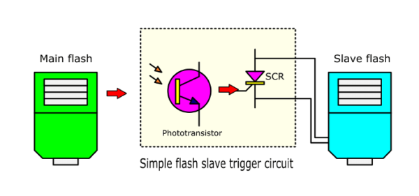
In-circuit there is phototransistor or solar sell get a light of the flash to control the SCR run the slave flash works.
We have 2 circuit ideas about this:
Simplest Flash slave trigger circuit
First, it is simplest circuit and cheap. It will help the slave flash immediately works almost simultaneously with the main flash. This circuit better than other circuits because without the external power supply.
The Working of Circuit
Since (look at the circuit below) use the solar cell to get light from the main flash. The solar cell will have the voltage to trigger the gate lead of thyristor (SCR) Th1 to apply the slave flash works. This all operation use times less than 1/1000 second.
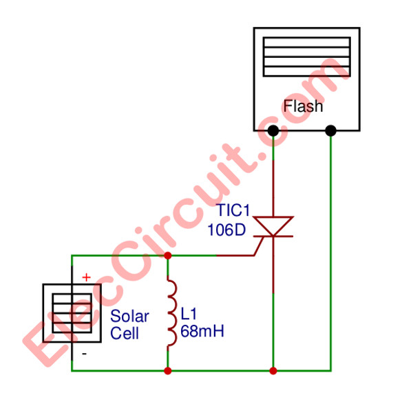
Figure 1: Simplest slave flash trigger circuit
- SCR1- TIC-106D is low power and high sensitivity and includes the choke to get the trigger voltage from the solar cell. Which should have an aperture area of at least 100 square millimeters.
- The shock coil of 68 mH that helps the circuit has high sensitivity and wide up.
- The prototype can be used in distance from the main flash to slave flash it makes up to 50 meters.
Recommended: Learn how SCR Works and using
What is more? The below circuit is better. Why?
The Extra flash slave trigger circuit
This circuit has more components than the first circuit. Also, This makes a general flash become 2 extra flash work together. Suitable in the case to add flash to remove shadows.
Same as the previous circuit. This circuit does not require an external power supply, too. This circuit consumes very little current Only microamps.
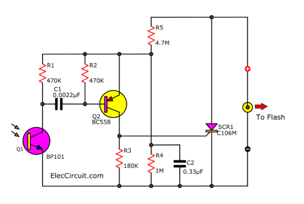
They only use the voltage from the flash at a trigger contact. which in some flash may have this voltage up to 150V to 200V.
Related: Phototransistor Relay switch
See in the circuit. This voltage is divided by R4 and R5 to be the appropriate voltage. And, C2 is a good decoupling filter to smooth voltage. Because this circuit consumes very little current only a micro-amp. So don’t worry about affecting the flash operation
How it works
When the flashlight drops on the phototransistor-Q1. The pulse voltage will drop across at R1. Then, C1 passes this signal to Q2. Then, it increases a higher signal to trigger a gate of SCR1. So, it runs to connect the trigger contact of flash works well.
The values of the devices in this circuit are calculated for normal flash operation. Which is not disturbed by light from other sources such as light bulbs or sunlight. But we should also block other light into the phototransistor
Check out these related articles, too:
- Understand these About xenon flash circuit Before It’s Too Late
- LED Flashers Circuits and Projects using transistor
- Simple Brake light flasher circuit
Parts you will need
0.25W Resistors, tolerance: 5%
R1, R2: 470K
R3: 180K
R4: 4.7M
R5: 1M
Ceramic Capacitors
C1: 0.0022µF 100V
C2: 0.33µF 100V
Semiconductors:
Q1: BP101, Phototransistor
Q2: BC558, 45V 100mA PNP Transistor
SCR1: 8A 400V SCR
Related flash trigger circuits
GET UPDATE VIA EMAIL
I always try to make Electronics Learning Easy.
Related Posts


I love electronics. I have been learning about them through creating simple electronic circuits or small projects. And now I am also having my children do the same. Nevertheless, I hope you found the experiences we shared on this site useful and fulfilling.