I am showing you a digital multimeter circuit using ICL7107.
We modify them from a normal DC digital voltage meter circuit to smart multimeter. It is so versatile available function.
For example, Measure DC voltage, ACV, DC Amp meter, AC Amp meter and as the Ohms meter, etc.
Try to build this project to use it really worth and fully enjoy.
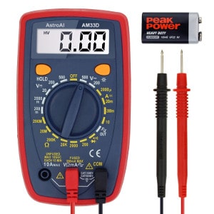
Thanks, Photo from the AstroAI Digital Multimeter. Why is a good tool? You can get an answer from here.
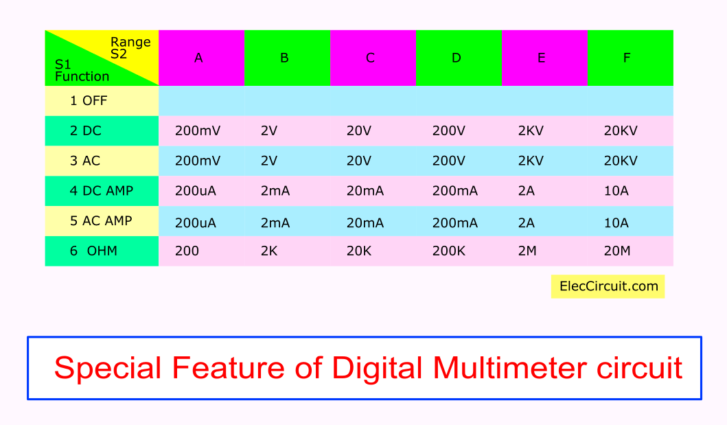
5 Special Features
- 1. DC Voltage: 200mV, 2V, 20V, 200V, 2KV, 20KV
- 2. AC Voltage: 200mV, 2V, 20V, 200V, 2KV, 20KV
- 3. DC Amp: 200uA, 2mA, 20mA, 2A, 10A
- 4. AC Amp: 200uA, 2mA, 20mA, 2A, 10A
- 5. Ohms meter: 200, 2K, 20K, 200K, 2M, 20M
Function 1: Digital DC voltmeter circuit
In Figure 1: the schematic diagram of this project. Of course, the easiest way is used as the DC voltage meter circuit.
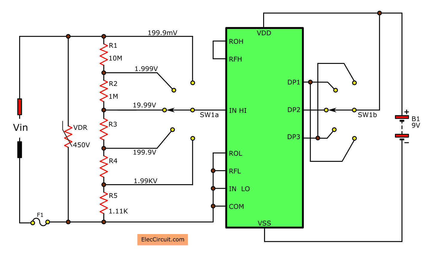
Figure1: DC voltage measurement circuit
The original characteristics of this circuit can measure voltages up to 200 mV only.
However, we can apply it to measure the voltage range higher with a few input resistors. See in Table 1:
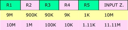
Table 1 is shown in the resistance at various ranges.
Note:
We may choose resistors in both formats.
For the too high voltage measurement. It is necessary to use the external high voltage probe.
R3 = 100K; R4 = 10K
Function 2: DC ampere meter circuit
Next, take a look at the simple digital DC ampere meter circuit. The appropriate designing, determine with resistance in parallel on the input of voltmeter.
The main principle to calculate.
The resistance is the voltage caused by the flow of current through the resistor. In each range is maximum up to 200mV.
As shown circuit diagram below.
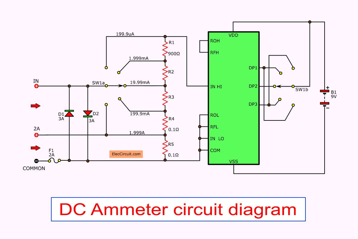
Figure 2: DC Ammeter circuit
See the circuit in Figure 2. Designing having a range of up to 5 range.
For the high current measurement 2 Amperes. You should separate it fro other input. Because the contact of switch that can not withstand currents.
Diode D1 and D2 are overload protection to provide the input.
Note: R2 = 90 ohms, R3 = 9 ohms
Function 3: AC voltage measurement
We can design the AC voltage measurement circuit. By adding the AC to DC converter circuit. They have a relationship together. As shown in Figure 3.
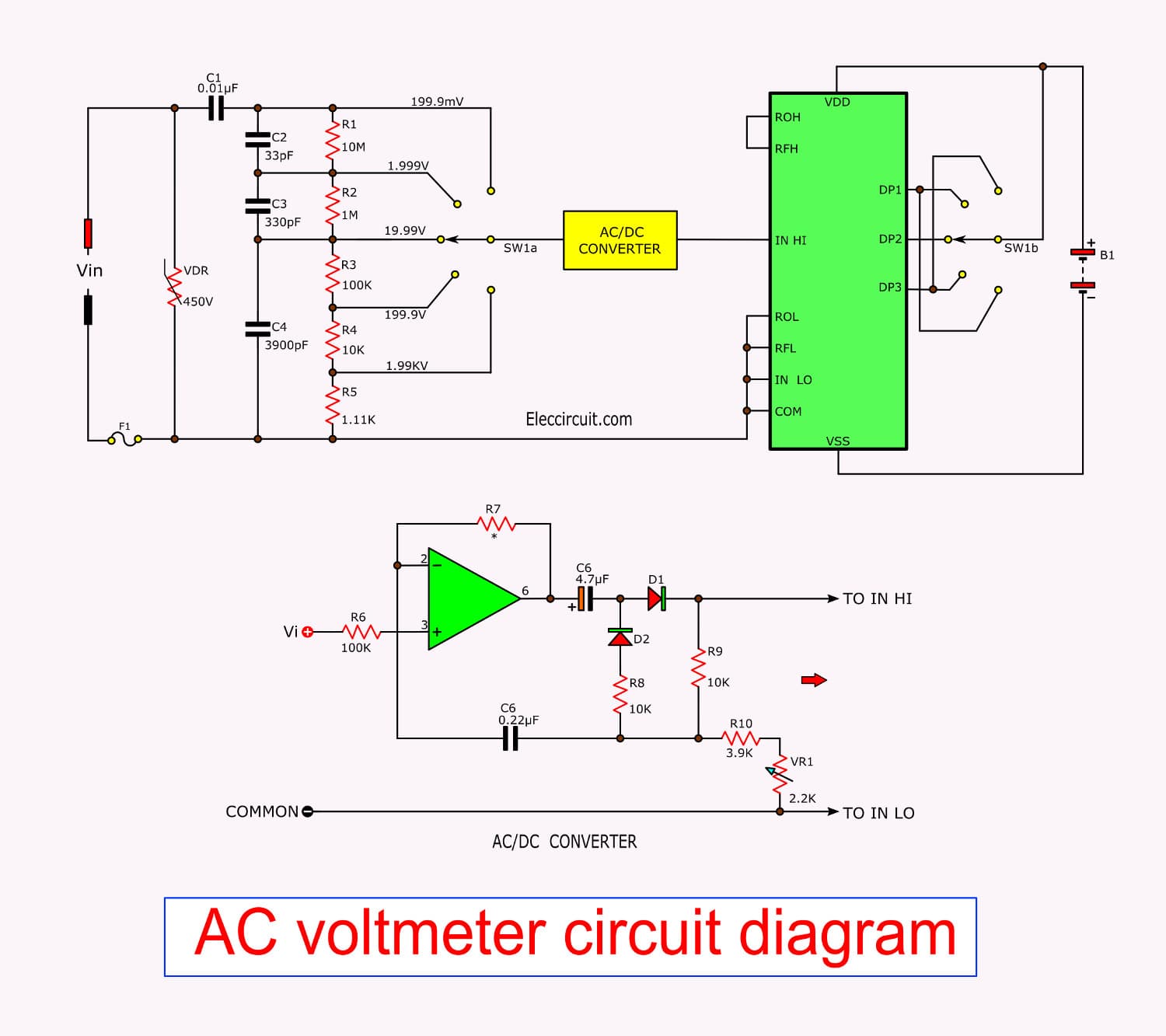
Figure 3: Digital AC voltmeter circuit without transformer
The AC voltage is measured to reduce voltage same the DC voltmeter circuit. Then, enter to the AC to DC converter circuit by IC1 and accessories in Figure 3.
Adjust VR1 to tune a correct voltage reading.
Function 4: AC Ammeter Circuit
The same principle applies to the DC voltmeter circuit. We can be applied to the AC ammeter by adding the AC to DC converter before as shown in Figure 4
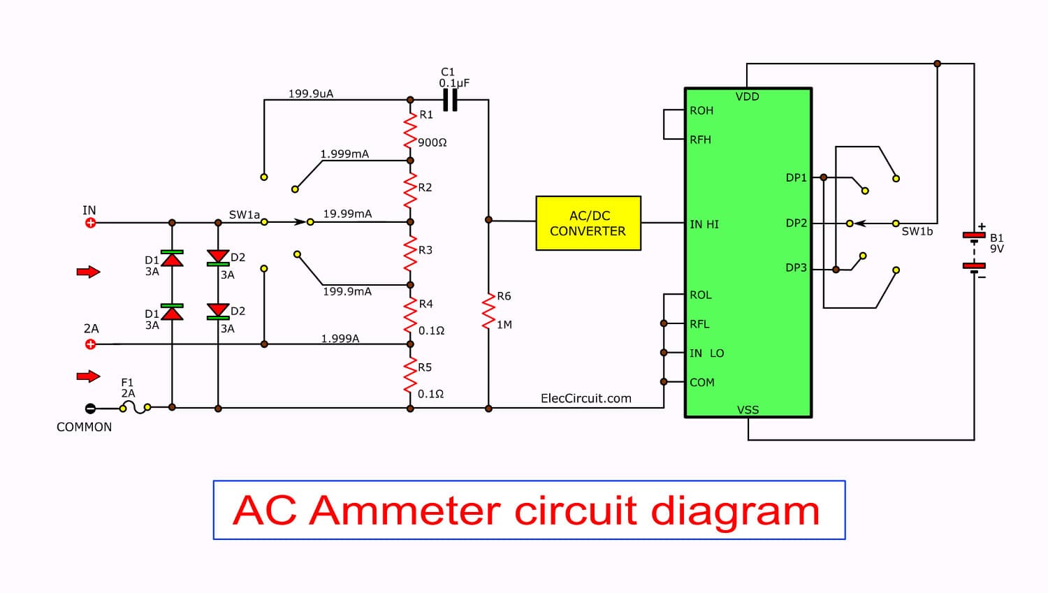
Figure 4: AC Ammeter measurement
Function 5: Ohms meter
The advantaged of this digital multimeter better than a regular meter:
This can read accurately. And can measure the resistance of 0.1 ohms or less. And higher as 10M easily.
With circuit connecting as shown in Figure 5.
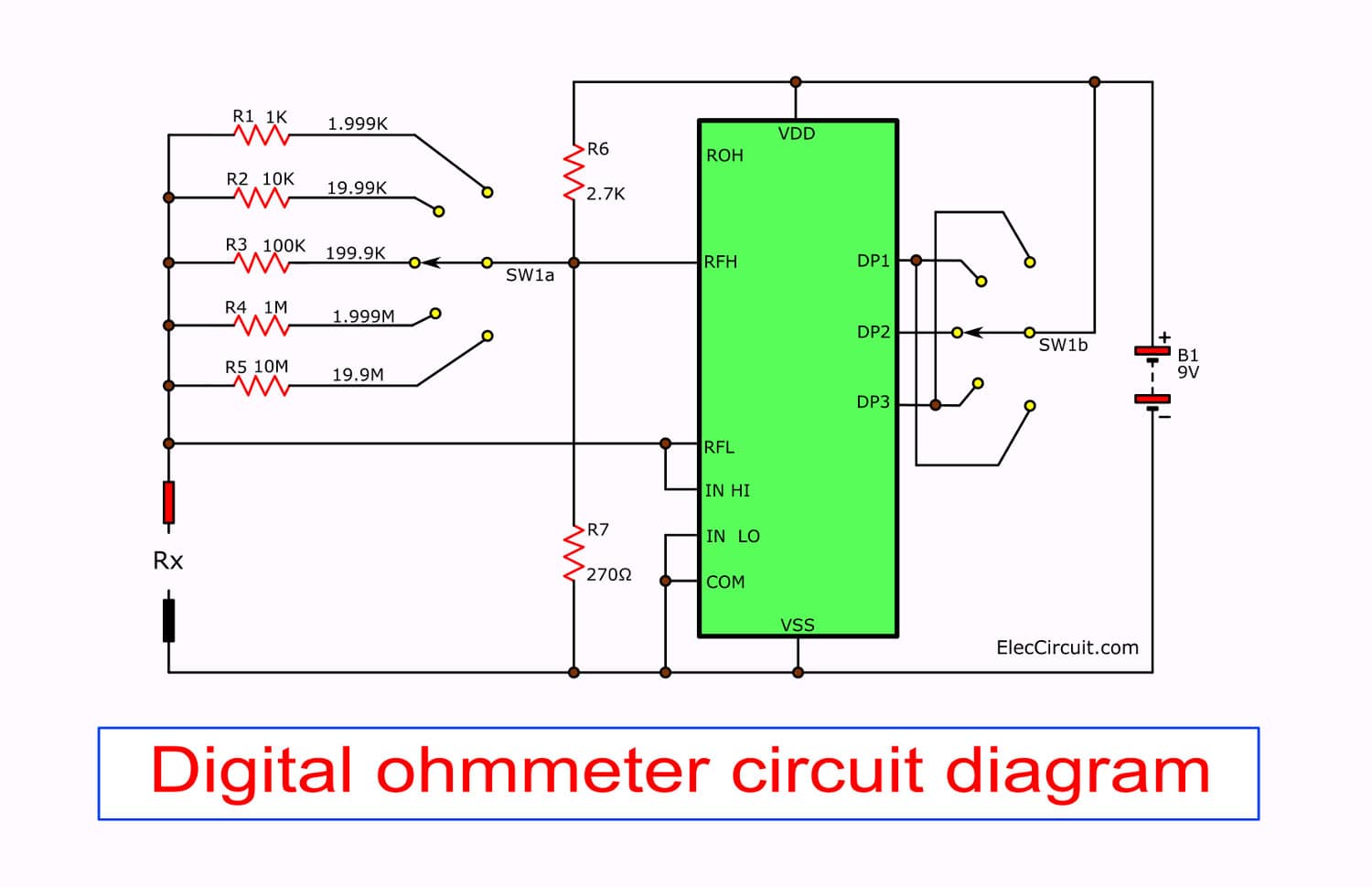
Figure 5 the ohms meter circuit
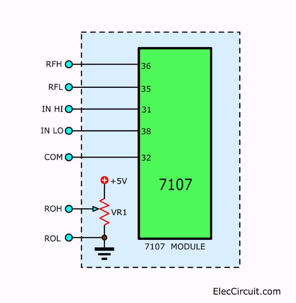
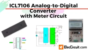
Figure 6 the ICL7107 module
The digital meter module in Figure 1-5 Show legs of ICL7107.
Compared to the legs of the modules to Easy to write all the circuits. The ROH pin is the output reference voltage at a middle leg of the horseshoe-shaped resistor.
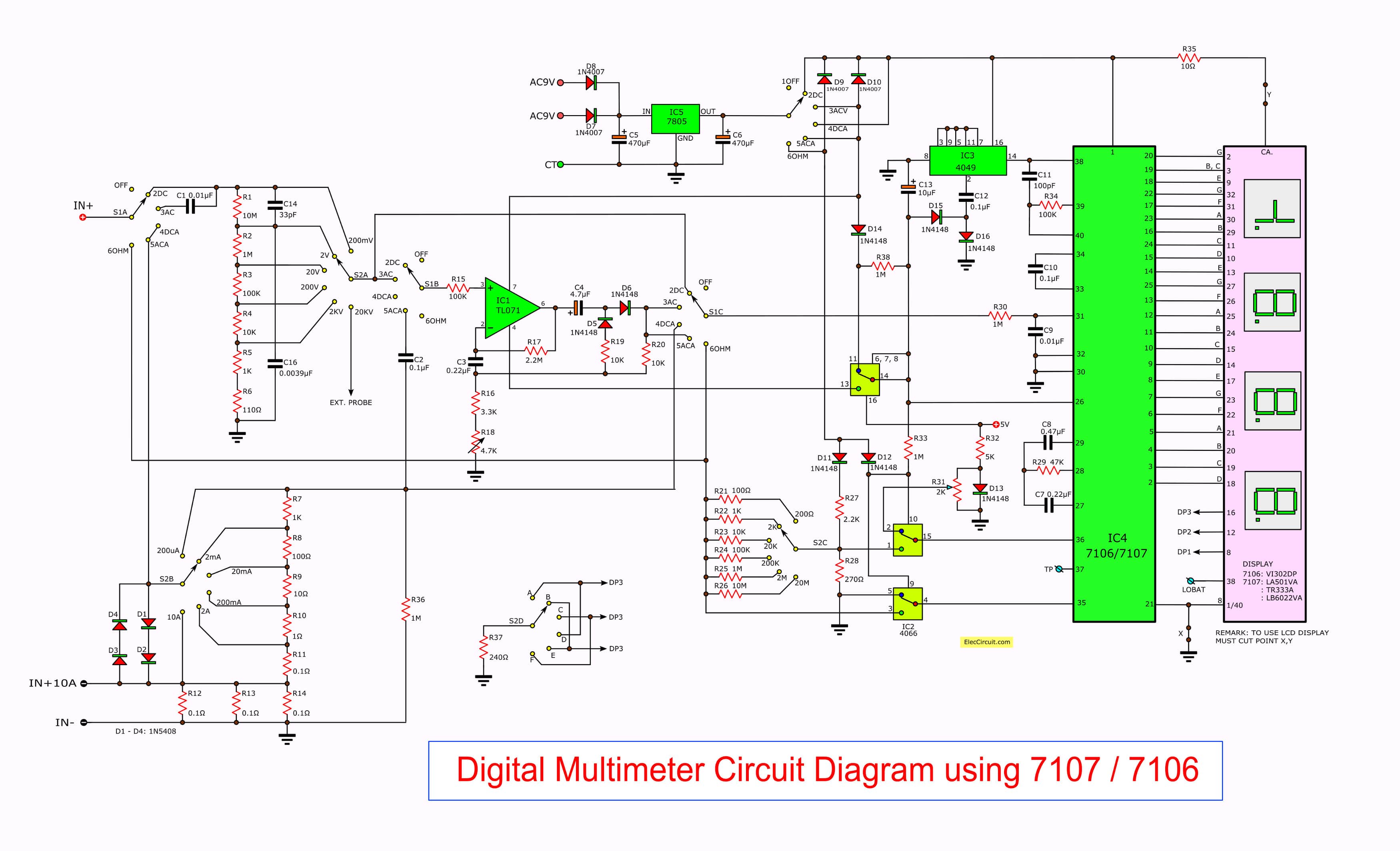
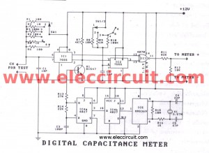
Figure 7: Full a digital multimeter circuit diagram
Here is a full circuit that works perfectly.
Parts you will needs
- IC1: TL071, Operational Amplifiers – Op Amps JFET Input Low Noise
- IC5: LM7805, Standard Regulator 5 Volt 1 Amp 3 Pin 3+ Tab TO-220
- IC3: CD4049, CMOS Hex Inverting Buffer/Converter
- IC2: CD4066, Quad Analog Switch/Multiplexer/Demultiplexer
- IC4: ICL7107 or ICL7106, Analog to Digital Converter Single Dual Slope 0.003k SPS 3 1/2 Digit LED 40-Pin PDIP
- LED 7 segment or LCD display
More Switches please read in a text
0.5W Resistors tolerance: 1%
- R1, R26: 10M
- R2, R25, R30, R33, R36, R38: 1M
- R3, R15, R24: 100K
- R4, R19, R20, R23: 10K
- R5, R22: 1K
- R6: 110 ohms
- R7: 1K
- R8: 100 ohms
- R9: 10 ohms
- R10: 1 ohm 1 watt
- R11, R12, R13, R14: 0.1 ohms 2 watts
- R16: 3.3K
- R17, R27: 2.2K
- R21: 100 ohms
- R28: 270 ohms
- R29: 47K
- R32: 5K
MKT capacitors
- C14: 33pF 63V
- C15: 330pF 63V
- C16: 0.0039uF 63V
- C11: 100pF 63V
- C10: 0.1uF 63V
- C9: 0.01uF 63V
- C8: 0.47uF 63V
- C7: 0.22uF 63V
- Electrolytic capacitors
- C5, C6: 470uF 16V
- C13: 10uF 16V
Diodes
- D1-D4: 1N5408
- D7, D8, D9, D10: 1N4001
- D5, D6, D11, D12, D13, D14, D15: 1N4148
Switch see in circuit and PCB layout
Digital voltmeter circuit »

I love electronics. I have been learning about them through creating simple electronic circuits or small projects. And now I am also having my children do the same. Nevertheless, I hope you found the experiences we shared on this site useful and fulfilling.
Awesome, Thanks.
Hi Ehsan,
You can send me email.
Thanks.
thanks for answer
my email: [email protected]
hi momename please send me a video from your project or a pdf file for more explore
thx for your answers
i need help with building the AC ammeter of 50 hz and i have to use leds to display my values
hello ,can you explain me more, i don´t understand the unions with the switches
Thanks
how many ic2 i need, and why one of them has pin 16?
Hi, there is a print mistake. It’s not cd4066, it’s cd4053.
Hello, what model of LED display is used here? I am looking at the schematic and It is saying LA601VA, but I cannot find any information on that model. Will something like the UN4043-13 or LFD5221-20/A-PF work just as well? Thoughts?
sorry I need more detail about this please help me brother
sorry I need more detail about this please help me brother send pdf or video to [email protected]
what is need of ic cd4049 in this circuit?
Please send me EAGLE design(pcb design) and tell me more about power supply used….email id:[email protected]
This circuit is awesome. I was planning on building a simple voltmeter but now I am going to give this more complex version a try. Thanks!
Mr have u become able to build it ???
I saw another digital voltmeter but using 3162 and unfortunately i could not find that Ic
The IC 2 has 14 legs, the bilateral switches will not work properly because wrong pinning, and diodes 9 a,d 10 are not mounteg at the pronted circuit..
als the lay-out is blurry.
Please in the future publish something working or don’t
grts,
Jean
Thank you very much. Very good
Thanks for important ckts.which helps us to understand electronic is a good way. 👍
Thank you. I’m so glad you found our website helpful. 🙂