This is a simple fiber optic intercom circuit. We will learn the basic principles of signal transmission through a fiber optic in a simple and saves.
Why use it?
Imagine a simple communication system in-home use. Such as Video Door Phone Intercom is going to happen in the future.
Or Meetings via the computer network with electromagnetic waves Or transmitting visual information, audio, and more.
By connecting through a conductive metal wire or electromagnetic waves. It’s complicated and quite low effective.
We find another way better. We found that light can take them to the same destination without distortion at all.
Read Back: Learning electronics for beginners with easy ways
The working principle
I believe that its history is not important to you. You might be more eager to learn how to use it.
Of course, this intercom circuit has both receiver and transmitter, which looks like a general intercom circuit. See below.
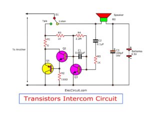
Also: Simple transistor intercom
Transmitter
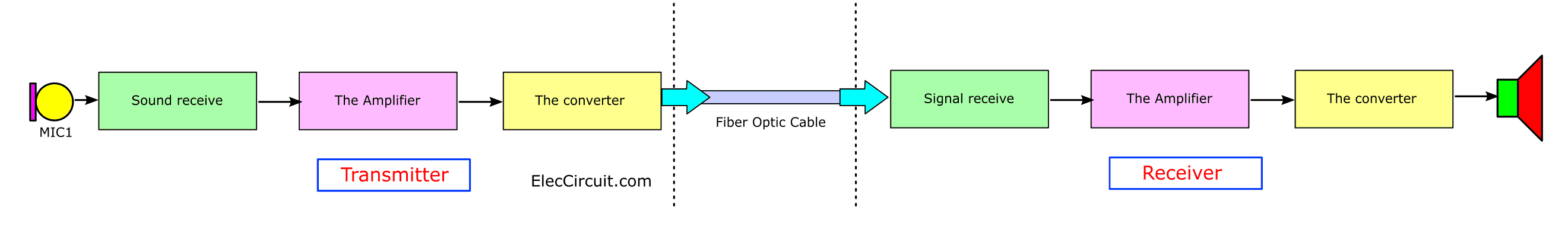
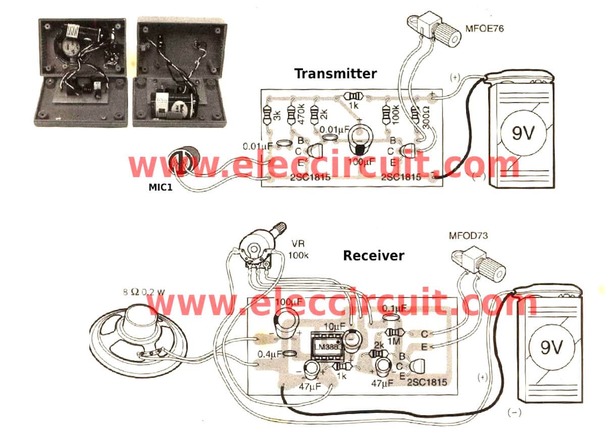
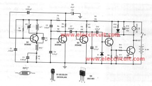
First, In figure 1 The circuit is divided as 2 main section are transmitter and receiver.
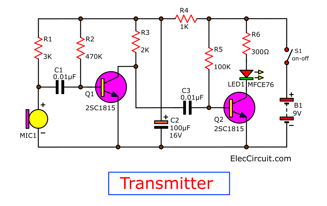
First, look at the transmitter circuit below.
A MIC1 act as the sound receiver once we talk to a microphone, the voice is converted to the electrical signal.
Then, a capacitor C1 passes a fluctuating signal to bias a transistor Q1. But the signal gets from the output of Q1(2SC1815) still not higher enough.
So, We need to increase it more using Q2(2SC1815).
After that, the signal is sent to the MFOE76 photodiode(LED). To convert electrical signals into optical signals. It is a red light that we can see.
What is more?
The receiver
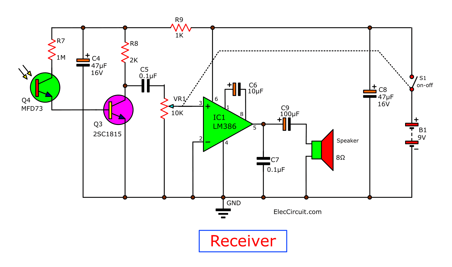
The receiver consists of 3 parts are : 1. the signal receiver 2. the amplifier and 3. the converter.
In the receiver section, the MFOD73 photo transistor act gets the optical signals from the transmitter through the fiber optic cable.
Here are a few related posts you may find helpful, too:
- Infrared Intruder Alarm circuit diagram
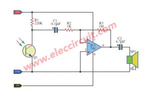
- Learn audio transmission with light
- How does NE555 timer circuit works | Datasheet | Pinout
Then, the optical signals are converted to electrical to bias with the Q3(2SC1815). But the signals have a weak voltage. Not enough to drive the speakers.
We need to use the LM386N amplifier to increase up the signal strength. The VR1 is adjusted with the volume of the signal.
How to assemble the circuit
As both, the transmitter and receiver circuits are separated from each other. We need to create two units is one transmitter and one receiver unit. Each device will use a 9-volts battery for power a voltage to the circuit.
Others: Fiber Optic Intercoms
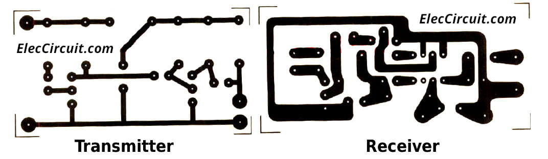
First, make two PCBs. See the characteristics copper pattern is shown below.
So what?
Parts you will need
0.25W Resistors, tolerance: 5%
- R1: 3K
- R2: 470K
- R3, R8: 2K
- R4, R9: 1K
- R5: 100K
- R6: 300 ohms
- R7: 1M
- VR1: 10K, Potentiometer
Electrolytic Capacitors
- C4,C8 : 47uF 16V
- C6: 10uF 16V
- C2, C9: 100uF 16V
Ceramic Capacitors
- C1, C3: 0.01uF 50V
- C5, C7: 0.1uF 50V
Semiconductors, others
- Q1,Q2,Q3: 2SC1815, 50V 150mA, NPN Transistor or equivalent
- IC1: LM386, Audio Amplifier IC
- B1,B2: 9-volt batteries
- SP1: 8 ohms 0.25” Speaker
- MIC1: Condenser MIC
- S1, S2: SPST Slider Switch
See the soldering equipment. Be careful leg devices, transistors, ICs, capacitors. We need to place them correctly.
Then, solder the wires to the external device attached to the box. On the prototype using the versatile box. Which can be mounted PCB to fitted.
Read also
- IR – infrared receiver circuit
- Cheap & Small hearing aids circuit project
- How to install CCD camera sensor with VHF sender
See DIY fiber optic intercom circuits on PCB.
Applications
We can use it as a general intercom. However, this project is a one-way intercom. so, we can send the audio signal only.
And that important, Using a fiber optic transmission. We should be careful not to make the twisted fibers within it may be broken.
And should not be using too long. Because it is implemented in a simple way. No repeater station.
In an experiment at a distance of 14 feet the sound quality is also good. So it may be using fiber optic cable was longer.
Applications may be used as a tool for communication between one room to another room that was around the same time.
Note: This project is only an example of a concept. Therefore did not confirm the actual work
Here are a few related articles you may want to read:
- 3 Intercom circuit using LM386 – OP-Amp ICs
- FM wireless microphone circuit diagram
- Simple Two Transistors AM Transmitter Circuit

I love electronics. I have been learning about them through creating simple electronic circuits or small projects. And now I am also having my children do the same. Nevertheless, I hope you found the experiences we shared on this site useful and fulfilling.

Hi!
Awesome project, congrats!!!
Can I send the audio signal by fiber optic for 100m (300 feet) with your circuit (without repeater stations)?
With best regards, Nick from Kiev (Ukraine)
Hi,Nick Kiev
Thanks for feedback.
Thanks for posting this awesome article. I’m a
long time reader but I’ve never been compelled to leave a comment.
I subscribed to your blog and shared this on my Facebook.
Thanks again for a great article!