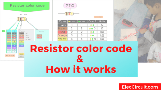
A resistor is the most common and useful component in electronics, so let’s learn more about them. For instance, getting to know the resistor color code, learning how to read them, and knowing some standard resistor values will make using them much easier.
We use resistors in almost every electronic circuit, and they are also an essential part; without them, most circuits would not function. But how does it work, and what is it used for? See a simple summary below to understand more.
What Is a Resistor?
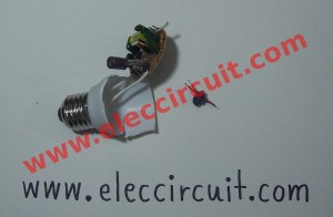
First, let’s get to know the resistor, what they look like in real life, and their electronic symbol used in circuit schematics. The image below shows actual resistors with their wattage rating.
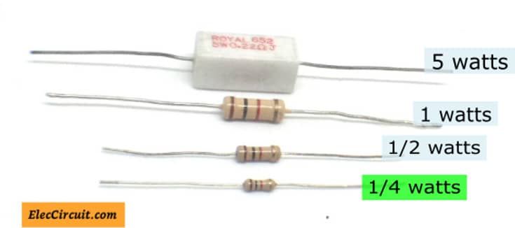
Lower-wattage resistors resemble a worm with vertical color stripes and wires coming out of each end, whereas the higher-wattage ones may come in a white rectangular block with two wires. We use the smaller ¼-watt one most often of the four shown above.
The illustration below shows the symbol of a resistor. Generally, there are two distinguishing styles depending on the region. The “my style” referred to the symbol we use for a resistor in our circuit schematics.
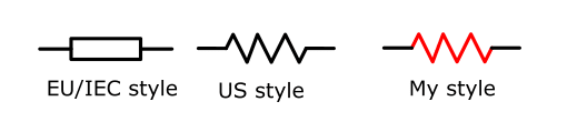
You can learn more about electronic symbols here.
What Does a Resistor Do?
The resistor resists or limits the current passing through it. The amount by which it resists the current is known as its “resistance.” A resistor with a higher resistance will only allow a small amount of current through. Let’s compare the current to water in a pipe.
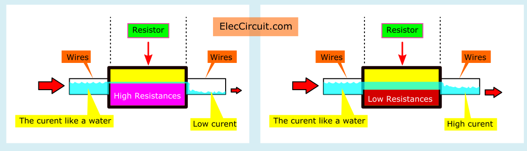
- The resistor on the left has a high resistance, and thus the current flow through it is limited.
- On the other hand, the right resistor has a lowresistance, allowing current to flow more freely through it.
Different Ways to Use a Resistor
“Why do we need a resistor?” you might ask. Since we already know that the purpose of a resistor is to limit current flow in a circuit, let’s look at some of its applications that utilize this feature.
- Using the resistor in a series circuit.
- A resistor can reduce the current that flows through an LED. Which can get damaged with too much current.
- It can also be used as a voltage divider to divide a voltage into a smaller one.
- A resistor is used to increase the time required to charge a capacitor or speed up the discharge of one in an RC circuit.
- A resistor is also used to control the gain of amplifiers.
Resistor Color Code
Notice that most resistors have color bands printed on their bodies; these color bands indicate the resistance of a particular resistor. The resistance of a resistor is measured in units of ohms, also represented by an omega symbol (Ω).
As 1Ω is a relatively small value for resistors, we often give them suffixes like kΩ or MΩ. For example:
1kΩ =1,000Ω
10kΩ = 10,000Ω
100kΩ = 100,000Ω
1MΩ =1,000,000Ω.
But why bother using the color code at all? Because resistors are small components, printing the whole resistance value on them might not be possible. It can be hard to see at first glance, but these color bands are color-coded to tell resistance values, so let’s see what each color band tells us about its value.
Resistor Color Code Calculator
For starters, most resistors have four color bands, including 0.25 watts, 0.5 watts, 1 watt, and 2 watts. When I was a young boy, I used to see a three-color band as well, especially on an AM radio receiver.
In the table below, the first two colors represent 0-9 numbers. The third color band is the modifier for the aforementioned numbers. Lastly, the fourth color band represents the tolerance, or probable deviation from the specified value.
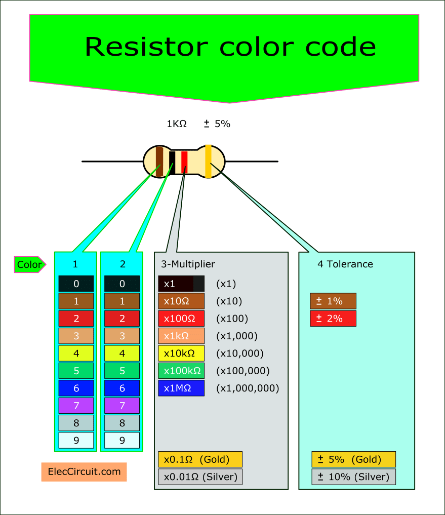
For example, suppose that we have a resistor with colors of brown, black, red, and gold. How much would its resistance be?
The first and the second color bands are brown and black, respectively. In the table above, brown is “1” and black is “0,” meaning that the number is “10.”
The third color band is red, which is a ×100Ω modifier. Therefore, the resistance of this resistor is 10 × 100Ω = 1,000Ω, or 1kΩ.
The fourth color band is the tolerance of the resistor, and gold means that the tolerance is ±5%. As a result, the actual resistance value of our 1kΩ resistor is between 950Ω and 1050Ω.
Additionally, to easily determine which color band is the first band, notice that the last band—the tolerance band—is a little bit further from the rest, and it is often gold or silver in color. Using this, we can infer that the opposite band is the first band.
How to Read Resistor Color Code Without Calculating
Another way to decode the resistor color code is to use a table like the one shown below. Where we do not have to calculate with the modifier, instead we can just place the number from the first two color bands in formats determined by the third color band, and then add a corresponding unit at the end.
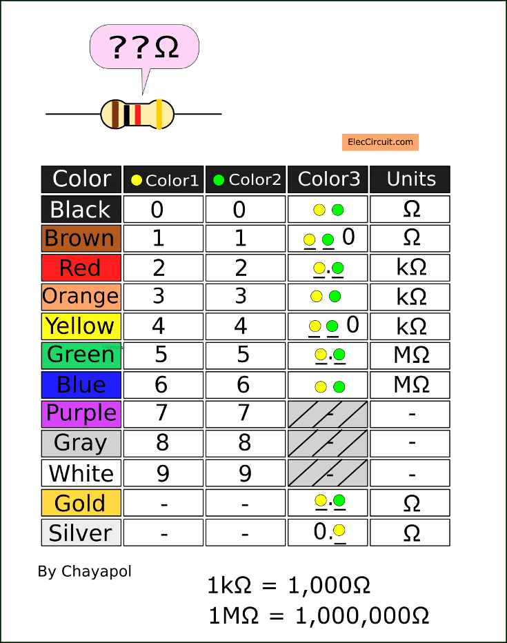
Let’s practice with 6 different resistor color codes. The last color in all of these color codes will be gold, meaning that they will all have a 5% tolerance. You can also practice using the following examples from below. Let’s begin!
The first resistor—Brown, Black, Red, and Gold.
Brown and black represent 1 and 0. The third color band is red, so we put a dot between the number of the first color and the second color, getting us 1.0. Then we put a kΩ as its unit, resulting in a value of 1.0kΩ or 1kΩ.
The second resistor—Yellow, Purple, Red, and Gold.
Yellow and purple represent 4 and 7. The third color band is red, so we put a dot between the number of the first color and the second color, getting us 4.7. Then we put a kΩ as its unit, resulting in a value of 4.7kΩ.
Third resistor—Orange, Orange, Orange, and Gold.
Orange and orange represent 3 and 3. The third color band is also orange; thus, we do nothing. Then we put a kΩ as its unit, resulting in a value of 33kΩ.
Fourth resistor—Red, Red, Yellow, and Gold.
Red and red represent 2 and 2. The third color band is yellow, so we put an extra 0 at the end. Then we put a kΩ as its unit behind the 0, resulting in a value of 220kΩ.
Fifth resistor—Brown, Black, Gold, and Gold.
Brown and black represent 1 and 0. The third color band is gold, so we put a dot between the number of the first color and the second color, getting us 1.0. Then we put an Ω as its unit, resulting in a value of 1.0Ω or 1Ω.
Sixth resistor—Green, Black, Silver, and Gold.
Green and black represent 5 and 0. The third color band is silver, so we put 0. in front of the number of the first color, getting us 0.50. Then we put an Ω as its unit, resulting in a value of 0.50Ω or 0.5Ω.
Standard Resistor Values Table at 5% Tolerance
The table below shows standard resistor values for carbon film resistors with 5% tolerance.
| 1Ω | 10Ω | 100Ω |
| 1.1Ω | 11Ω | 110Ω |
| 1.2Ω | 12Ω | 120Ω |
| 1.3Ω | 13Ω | 130Ω |
| 1.5Ω | 15Ω | 150Ω |
| 1.6Ω | 16Ω | 160Ω |
| 1.8Ω | 18Ω | 180Ω |
| 2Ω | 20Ω | 200Ω |
| 2.2Ω | 22Ω | 220Ω |
| 2.4Ω | 24Ω | 240Ω |
| 2.7Ω | 27Ω | 270Ω |
| 3Ω | 30Ω | 300Ω |
| 3.3Ω | 33Ω | 330Ω |
| 3.6Ω | 36Ω | 360Ω |
| 3.9Ω | 39Ω | 390Ω |
| 4.3Ω | 43Ω | 430Ω |
| 4.7Ω | 47Ω | 470Ω |
| 5.1Ω | 51Ω | 510Ω |
| 5.6Ω | 56Ω | 560Ω |
| 6.2Ω | 62Ω | 620Ω |
| 6.8Ω | 68Ω | 680Ω |
| 7.5Ω | 75Ω | 750Ω |
| 8.2Ω | 82Ω | 820Ω |
| 9.1Ω | 91Ω | 910Ω |
| 1kΩ | 10kΩ | 100kΩ |
| 1.1kΩ | 11kΩ | 110kΩ |
| 1.2kΩ | 12kΩ | 120kΩ |
| 1.3kΩ | 13kΩ | 130kΩ |
| 1.5kΩ | 15kΩ | 150kΩ |
| 1.6kΩ | 16kΩ | 160kΩ |
| 1.8kΩ | 18kΩ | 180kΩ |
| 2kΩ | 20kΩ | 200kΩ |
| 2.2kΩ | 22kΩ | 220kΩ |
| 2.4kΩ | 24kΩ | 240kΩ |
| 2.7kΩ | 27kΩ | 270kΩ |
| 3kΩ | 30kΩ | 300kΩ |
| 3.3kΩ | 33kΩ | 330kΩ |
| 3.6kΩ | 36kΩ | 360kΩ |
| 3.9kΩ | 39kΩ | 390kΩ |
| 4.3kΩ | 43kΩ | 430kΩ |
| 4.7kΩ | 47kΩ | 470kΩ |
| 5.1kΩ | 51kΩ | 510kΩ |
| 5.6kΩ | 56kΩ | 560kΩ |
| 6.2kΩ | 62kΩ | 620kΩ |
| 6.8kΩ | 68kΩ | 680kΩ |
| 7.5kΩ | 75kΩ | 750kΩ |
| 8.2kΩ | 82kΩ | 820kΩ |
| 9.1kΩ | 91kΩ | 910kΩ |
| 1MΩ | 3MΩ | 9.1MΩ |
| 1.1MΩ | 3.3MΩ | 10MΩ |
| 1.2MΩ | 3.6MΩ | 12MΩ |
| 1.3MΩ | 3.9MΩ | 13MΩ |
| 1.5MΩ | 4.3MΩ | 15MΩ |
| 1.6MΩ | 5.1MΩ | 16MΩ |
| 1.8MΩ | 5.6MΩ | 18MΩ |
| 2MΩ | 6.2MΩ | 20MΩ |
| 2.2MΩ | 6.8MΩ | 22MΩ |
| 2.4MΩ | 7.5MΩ | |
| 2.7MΩ | 8.2MΩ | |
| 0.5Ω | 0.22Ω | 0Ω |
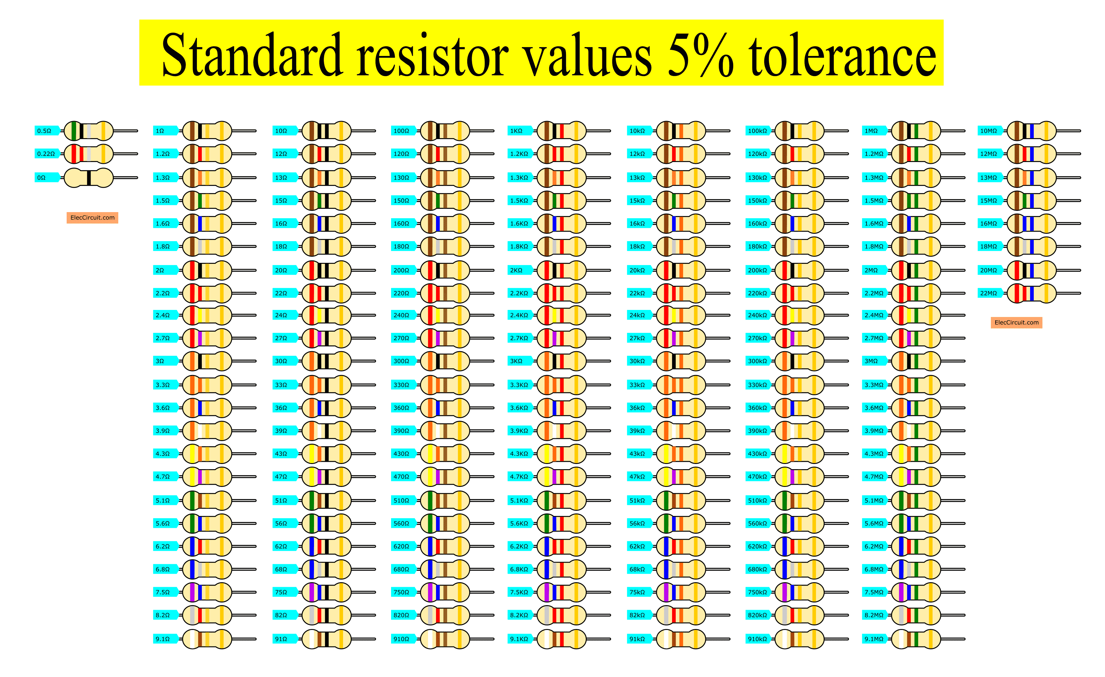
You could also see the color code on the resistor and its corresponding resistance value in the image above.
Decade Resistance Combination Picker
This is a simple tool that can produce every standard resistor value (E24 or below). It consists of multiple sets of four resistors connected in a star pattern, where the next set has ten times the values of the previous set.
How it works
Resistors are produced with preferred resistance values, which we call “standard resistor values.” Nowadays, resistors are produced with the E24 series of possible values, or 24 logarithmic steps per decade. In other words, it takes 24 logarithmic increments to reach ten times the value; for instance, 1, 1.1, 1.2, …(19 steps)… 8.2, 9.1, and then 10.
Therefore, reproducing all those values with just a handful of resistors is possible. For instance, considering the diagram below, it consists of 12 resistors in total. Using an alligator clip wire, we can choose a combination of resistors to achieve any value from 1Ω to 910Ω.
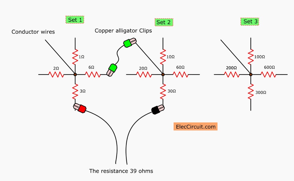
How to Use
For example, if the resistance we need is 39Ω, connect the resistors with 3Ω, 6Ω, and 30Ω in series as seen above; the total resistance adds up to 39Ω. Additionally, if your application calls for decimal resistances, you could round up to the closest values and use them instead. Alternatively, you could also add one more set with one-tenth the resistance values of the first set; i.e., 0.1Ω, 0.2Ω, 0.3Ω, and 0.6Ω.
The advantage of this setup is that it is cheap, simple to make, and accurate. Additionally, it does not require the use of a meter to adjust resistance, plus it can withstand a reasonable amount of current (depending on the wattage of the resistor in question).
However, there is also a disadvantage: the setup can take up a lot of space and get messy if it is not done properly. And since many wires are hanging about, it is also susceptible to accidental short circuits.
GET UPDATE VIA EMAIL
I always try to make Electronics Learning Easy.

I love electronics. I have been learning about them through creating simple electronic circuits or small projects. And now I am also having my children do the same. Nevertheless, I hope you found the experiences we shared on this site useful and fulfilling.

Thanks.
I have to thank you for your blog.as I am getting older and have very little education your article on lm317has made it simple to understand
Much respect to you sincerely
Lamont
Hi Lamont,
I am always happy. When the elderly said Interested in learning electronics. It makes our lives useful. Time passed quickly and everyone enjoyed. Also, the children liked it.
I will dedicate to writing the easiest readable articles.
It is good teaching! so easy to learn. Keep your job!
Thanks for your feedback.
I came across your article and learned something new today. Easy to understand, thank you!
Hello Meera,
Thanks for your feedback.
I found this site very useful.
Thanks for your feedback.