If we want a good quality sound system. The first thing that we should choose, a good preamplifier circuit. Some said It is not necessary. Let me explain to you why should you use transistor preamplifier circuits.
Why use preamplifier circuit ?
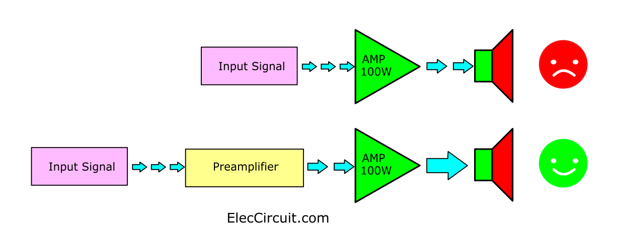
Imagine we have a 100 watts RMS amplifier. And the gain of about 22 times the input sensitivity or the input signal level of 1.2V.
So, we have to enter the 1.2Vp-p input signal to hear 100 watts of full power.
But if we enter the lower sound signal like 0.1Vp-p., It will cause the sound to be lowered into the speaker as well.
Therefore, we need to have a basic amplifier or preamplifier in order to amplify the signal to have enough power about 1.2Vp-p with low distortion.
In many cases, the amplifier needs different components such as gain, sensitivity, or even impedance matching.
We should learn or choose to create 4 preamplifier circuits in which each circuit uses only one transistor. And arrange different circuits To be consistent with the needs of the amplifier.
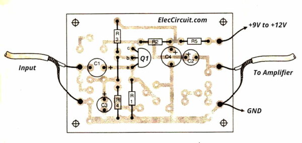
Note: All 4 circuits have the same PCB, so we can choose to position different devices for the selected circuit.
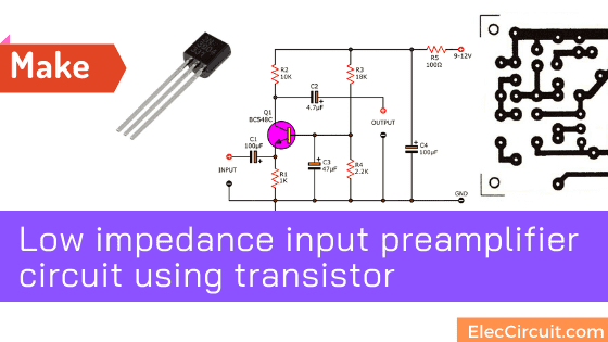
Low impedance input Preamplifier using transistor
I am going to show you a low impedance input transistor preamplifier circuit. Why should we make this circuit? Read before
In an old amplifier circuit, such as in an intercom system Use 2 or more speakers instead of a microphone.
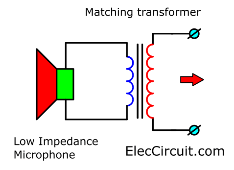
In this case, the voice coil of that speaker has a very low impedance, not more than 20 ohms only Voltage from the voice coil is very low, only less than 0.01V. And older AM radios also use low impedance speakers, too.
Recommended: Simple Transistor intercom project
We can increase impedance by using matching transformers. To convert both the higher impedance and voltage. But using transformers will lose high frequency. Therefore use transistor better.
The Common base amplifier or the circuit that connects the base to the ground. (Ground Bases). As in the example in the circuit diagram below is a low impedance amplifier of approximately 50 ohms.
Read first for beginners: How do transistor circuits work
How it works
When considering circuits We can distribute the details as follows
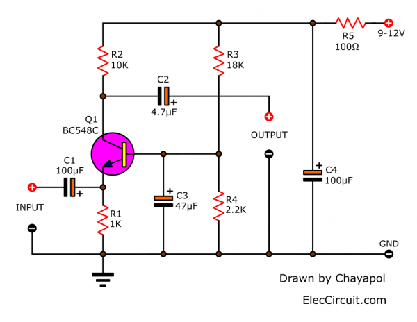
- Transistor-Q1 is an NPN transistor. So, its power supply circuit is + VCC power, by using the + 9V to + 12V power supply through R5 before. And, there is C4 maintain stability as a decoupling to prevent any spike signals.
- R1 and R2 act as the input and output of the transistor.
- The transistor conducts current or amplifies the signal. There must be a bias between the lead base and emitter. The voltage of the base must be higher than the lead emitter.
Therefore use voltage divider circuit with R3, R4 to act as biased of the transistor. - Capacitor C1 is a signal coupling on the input and prevents DC voltage or noise-free pulses from the front circuit to this circuit.
Recommended: How to use capacitor coupling - The capacitor C2 is signal-coupling to output and prevents the DC voltage from disturbing the next circuit.
Read Also:
- Video amplifier splitter using transistor
- 7 Simple audio amplifier circuit
- Cheap & Small hearing aids circuit project
Customization and experimentation methods
This time it is a test play, supply low voltage test first. And then measure the voltage at the collector lead of Q1. Without entering the signal. We should read half the voltage of the power supply.
If you want the voltage at this point to be greater than half We can do this by changing the value R3 to more values.
If using 9 volts power supply, R3 should be at 6.8K. But If using 12V power supply we should R3 is 12K.
Hum high-frequency protection
The low impedance circuit as the circuit diagram is an easy hum. Especially the signal cables that are twisted together may cause alarms easily.
If high-frequency noise occurs, it is called RF Interference. We use the 0.1uF capacitor at the emitter (E) of transistor Q1 down to the negative voltage (or 0 volts) and in the PCB the device hole is designed to add this device already.
How to build it
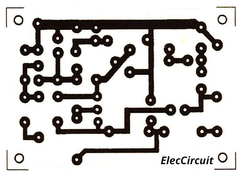
Look at the Actual-size of Single-sided Copper PCB layout below. And the component layout, too.
Check out these related circuits, too:
Parts you will need
0.25W Resistors, tolerance: 5%
- R1: 1K
- R2: 10K
- R3: 18K or See text
- R4: 2.2K
- R5: 100 ohms
Capacitors
- C1, C4: 100uF 25V Electrolytic
- C2: 4.7uF 25V Electrolytic
- C3: 47uF 25V Electrolytic
- C: 0.1uF 50V Ceramic
Semiconductors
- Q1: BC548 or equivalent, 45V 0.1A, NPN Transistor
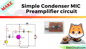
A Microphone From Normal Speaker
We sometimes need a Simple microphone, But we cannot find it. This circuit can help us modify the normal small speaker to the microphone as a pre-mic circuit.
This is the generally Microphone Preamplifier circuit. When entering the power supply circuit for Q1 will work as an amplifier in a common base.
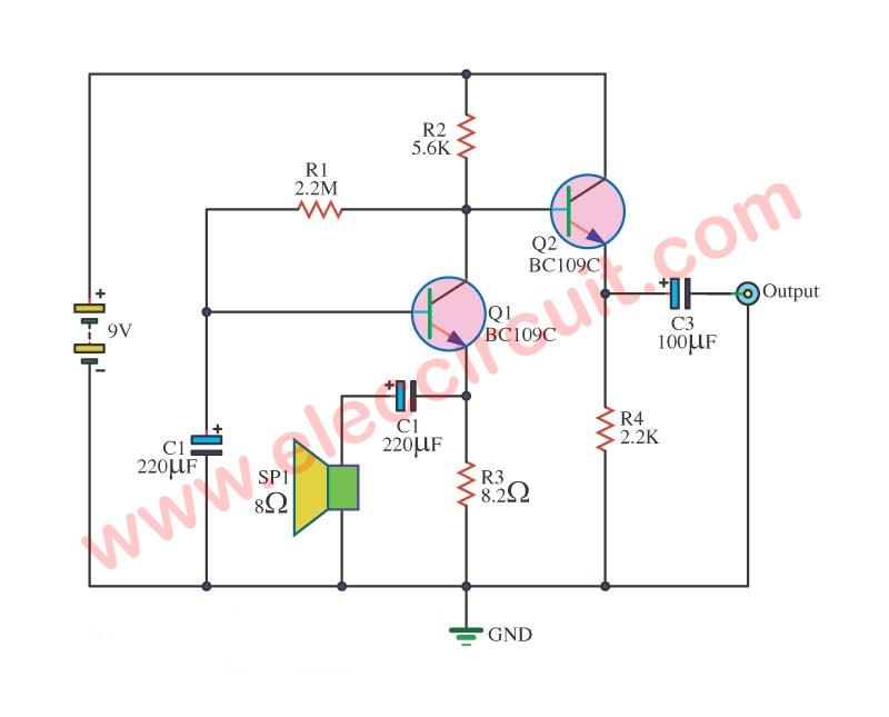
Microphone speaker circuit
That matching the input impedance of the Impact of Impact Speaker impedance low. When the signal sounds into the speakers. The audio is converted to electrical signals through C2. In addition, C2 to prevent voltage direct current flows into the speaker.
The signal that goes through C2 drop across R3 is a voltage signal sound. When Q1-BC109 works, will result in pressure changes pin B of Q2.This is the amplifier changes, the current implementation of Q2 change. If the speaker signal to drop across R3 is positive.
The Q2 will be very current. If the incoming signal is negative, Q2 will be less current. The output is a voltage drop across R4. The C3 protects DC, not to flow into the.
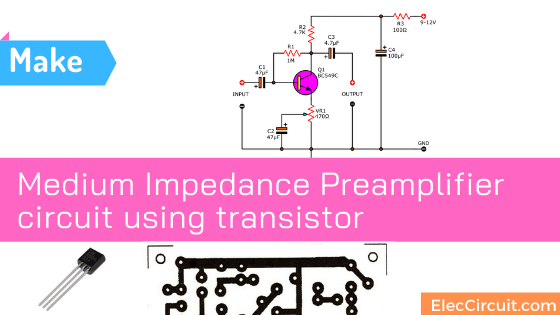
The medium Impedance Preamplifier circuit
If we want to design a Medium Impedance Preamplifier circuit using only one transistor We should change it into a common emitter.
This circuit has an input impedance of about 1.5K and an output impedance of about 4.7K. We can think from the load at the output. It is the value of R2 which is 4.7K.
Look at the circuit diagram.
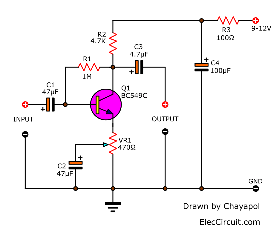
How it works
When considering the arrangement of the circuits as shown in the circuit diagram, it is found that the power supply is 9 volts. It will flow through the decoupling devices consisting of R3, C4 before.
Then, it supplies the positive voltage to the lead collector (C) of Q1, with R2 as a load of this part.
At the pin base (B) of the transistor requires a positive voltage when compared with the pin emitter(E). But it is positive lower than colletor just a little bit.
So, We use an easy way that takes R1 pass the voltage from pin collector into the base.
We called this that self-bias or negative feedback bias. Which it is a method of bias that can be varied according to the power supply of the circuit.
The emitter pin uses VR1 to act as a bias. With C2 to bypass the gain ratio. We designed this circuit can change the rate of extension. By moving the bypass point to increase or decrease the gain of the circuit according to the input from the audio source.
We are able to use other transistor numbers – they need to have a sufficiently wide hFE gain of about 10 to 160 times.
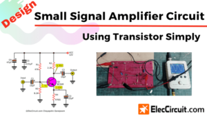
Learn: Designing small signal amplifier circuit using transistor simply
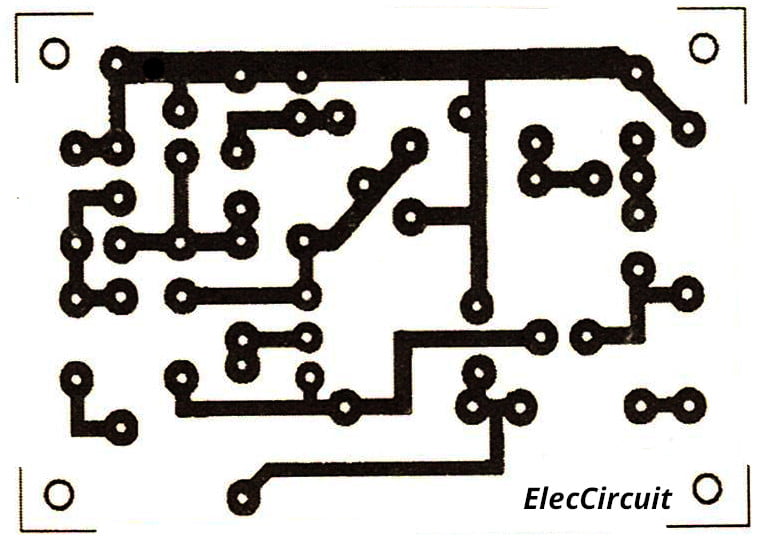
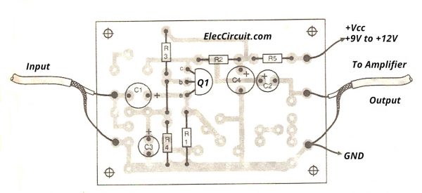
How to build
We can assemble this circuit on universal PCB or make an Actual-size of Single-sided Copper PCB as the layout below.
Parts you will need
0.25W Resistors, tolerance: 5%
- R1: 1M
- R2: 4.7K
- VR1: 470 ohms
Capacitors
- C1, C3: 4.7uF 25V Electrolytic
- C2: 47uF 25V Electrolytic
- C4: 100uF 25V Electrolytic
Semiconductors
- Q1: BC549 45V 0.1A, NPN Transistor
Basic Adjustment
When we have all the equipment And all the equipment has been installed, let’s test.
If we adjust VR1 go to the voltage 0V. It will create a voltage gain of about 8 to 10 times. When the hFE of a transistor is 110 to 600 times.
If we adjust VR1 go to pin emitter, the voltage gain will be 80 to 100 times.
The current of the 9V power supply is not less than 1.25mA.
Read Also:
Hum and noise Protection
The input of this circuit is designed to add the capacitor. See in the PCB. To solve the problem of RF frequency interference, too.
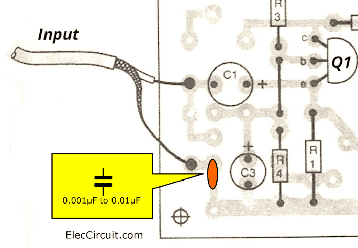
By connecting the input point (connecting the input signal cable). Put the capacitor into the hole of the PCB. Which we designed, It is approximately 0.001uF to 0.01uF.
Not only that see a good idea below
The single transistor phase shifter
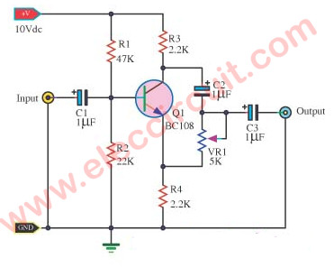
This is a basic NPN transistor circuit that provides a simple means of obtaining phase shifts between zero and 170 degrees. The BC108 transistor works as a phase splitter, the output at point A being 180 degrees without phase from the input. Then Point B is in phase with the input phase. Adjusting R1 gives the sum of different proportions of these and from now a successively variable phase shift. The circuit operates perfectly in the 600Hz to 4kHz range.
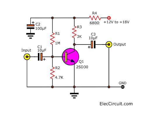
Pre Amplifier Circuit Diagram using a transistor
It is interesting because using only one transistor. If you do not have this one (2SD30). You may use others such as 2SC1815 or 2SC945 or 2SC828, etc.
Pre Amplifiers circuit Diagram using Transistor
The circuit above is a Mono system. If you want a stereo. You need to build another one Mono. Which this is an easy circuit.
We can connect the output of the circuit to the input of power amplifiers. For the input signal should be enough high level such as from CD player, cell phone, and more. It is not suitable for a low signal. Because of low gain.
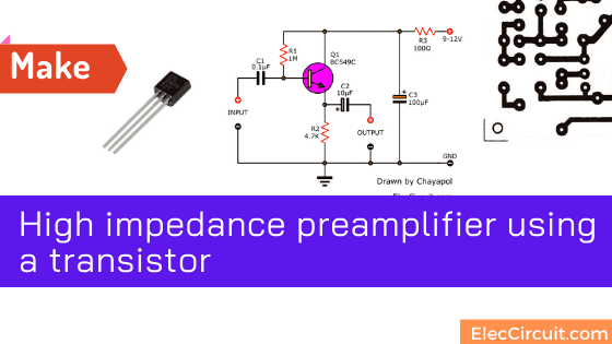
High Impedance Preamplifier circuit
Want a high impedance preamplifier circuit? For a ceramic record player, etc. Make the emitter follower circuit has low noise causes sound concise.
Of course, we like choosing simple and cheap circuits, this circuit too.
See the active circuits below. It’s a simple circuit. READ MORE
If we want to increase the input impedance of the bipolar circuit even more. We can make easy with 2 or 3 transistors, like the amplifier circuit on the tape radio. That is commonly used.
See below for example circuits.
Simple pre-amplifier using BC547 transistors
This is a higher preamplifier circuit. Also to increase a small audio signal to strength to go into a power amplifier circuit.
It is suitable for a tuner, tape, etc. That was the strength of input signals in μV to rise to mV. It can access efficiently to a power amplifier.
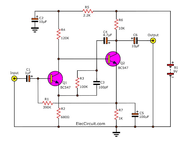
How it works
First of all, enters a 9V power supply to the circuit. Both Q1 and Q2 to a direct coupling circuit to transmit better.
When the signal input through the C1 coupling into the signal to Q1. It amplifies a signal to a higher level at the collector(C).
Then, the signal comes into Q2 as the second amplifier. Next, the signal to leave the output C of Q2. To pass the C6 coupling signal from the output. And some signals at the output of Q2 will feedback through to the C4, C3, and R3. It comes to pin E in Q1 in order to help the range of frequency response.
Simple Preamplifier Circuit using BC548 Transistors
This preamplifier circuit with two transistors. It uses a single supply source from 6V to 12V, at the current minimum is 2-3 mA. It can extend the signal strength max 2V.
This will drive easily a signal to a power amplifier. The frequency response is from 70 Hz – 45 kHz at -3 dB. It has a distortion of less than 0.1%.
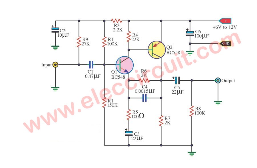
How it works
To begin with enters a supply voltage to the circuit. Second, to bring an audio source to Input. The signal is coupling through C1 to prevent DC voltage to disturb in the circuit.
Then, audio goes into the lead B of Q1 to amplify signals to forces up, with the R1 and R2. They are the organized bias for Q1. Both Q1 and Q2 transistors connect together in a direct coupling form, to improve audio response.
Next, the signal is increased out of lead C of Q2, and through C5 coupling the signal to smooth up. Then, send it to output. The gain of the circuit can be set from the R6/R5.
For capacitor C3 to improve a high-frequency response better.
Resistor-R9 brings a supply voltage and limits the current to connected to the circuit when the circuit for the condenser microphone. If you do not use it can remove R9 away.
Cassette Preamplifier circuit using a BC109 transistor
This is the circuit Cassette Preamplifier. I used transistor BC109 main part electronics.
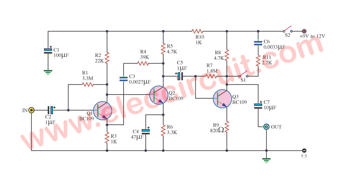
It is a very easy preamplifier for cassette tape or car audio. But is an old circuit, I like this circuit because it is classic.
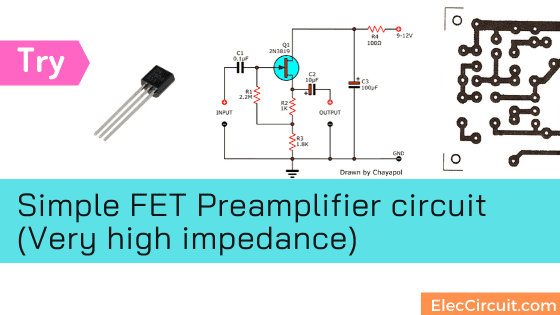
Try a simple FET Preamplifier circuit (Very high impedance)
If you need a very high impedance preamplifier. We may see many circuits using transistors or ICs. But if we need a circuit that is small, easy, and economical. I think the FET Preamplifier circuit might be something to look for.
How does the circuit work
The circuit using a field-effect transistor or FET is shown in the figure below. First of all, The DC power supply powers via a Decoupling system consisting of R4, C3 like other circuits.
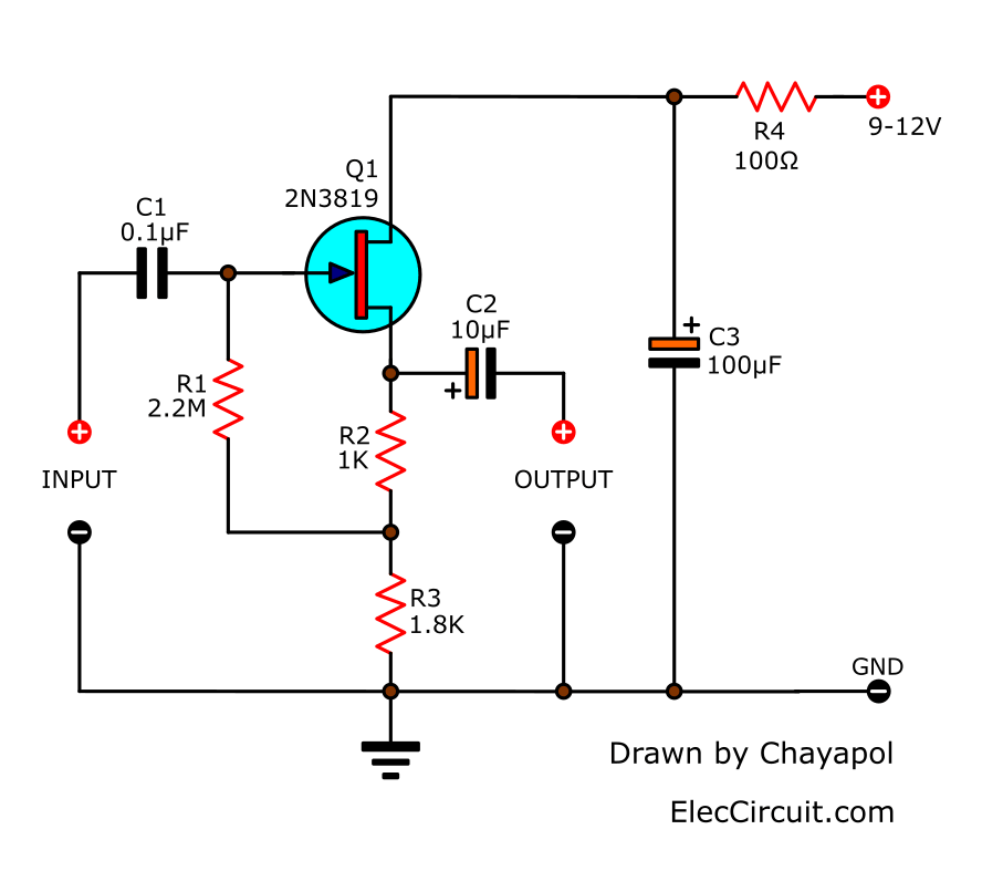
Then, the positive voltage enters the drain (D) While the gate (G) requires Bias as a negative electric potential. So, it takes R1 from the gate to the voltage 0 volts. But a direct connection causes uncertain bias control.
Learn more: how FET works (later)
So, We should use the improved bias method by connecting R1 to R2 / R3. Which they are the resistor on the source pin (S) of FET.
The voltage across the R3 is constant at about 3 volts. While the emitter pins of the transistor are generally equal to half the power supply.
Connecting the R1 to the gate like this. It is a built-in positive feedback system, also known as bootstrapping. Increasing the efficiency of the resistance Causes the input impedance of this circuit, to increase to about 6 magma ohms. The output impedance when the signal comes to around 500 ohms.
What is this circuit suitable for?
This FET preamplifier circuit is suitable for sending signals from the preamp to the amplifier circuit that uses long wiring.
We can change the resistance of R3 from 1.5K to 4.7K when using low voltage power supply.
How to build
If you want to try creating this circuit It is very easy. If we compared to general transistor circuits. You may solder equipment on the multi-purpose PCB. Or if using the same PCB as the original circuit. See the layout below. You will see that it is the same on all 4 circuits.
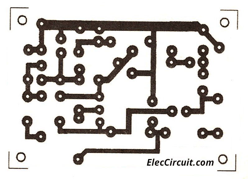
Actual-size of Single-sided Copper PCB layout
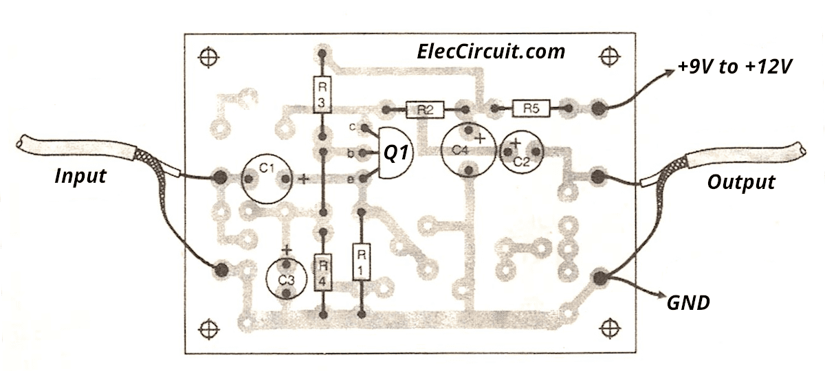
But the devices are positioned differently.
Parts you will need
0.25W Resistors, tolerance: 5%
- R1: 2.2M
- R2: 1K
- R3: 1.8K or see text
- R4: 100 ohms
Capacitors
- C1: 0.1uF 50V Ceramic
- C2: 10uF 25V Electrolytic
- C3: 100uF 25V Electrolytic
Semiconductors
- Q1: 2N3819 or equivalent, N-channel, Rf/VHF/UHF JFET
What is more? We always have many ways.
If above low gain for you. Look:
- SEE: Transistor preamplifier with Low noise Tone control
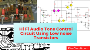
- Make the Best Hi Fi audio tone control circuit using transistors
- 3 Simple Audio Mixer Circuits diagram
- Dynamic Microphone Preamplifier circuit using C945
They have a tone control circuit.
Or
Try IC version: Preamplifier circuit using OP-AMP
GET UPDATE VIA EMAIL
I always try to make Electronics Learning Easy.
Related Posts

I love electronics. I have been learning about them through creating simple electronic circuits or small projects. And now I am also having my children do the same. Nevertheless, I hope you found the experiences we shared on this site useful and fulfilling.
Thanks a lot. It is working fine. Simple and elegant.
is it fine if I use it for 2.1 stereo system ?
please mail me 🙂
thanks anyway ,,,,
can you give the procedures and parameters in making this simple preamp by transistor.
i think i cannt get transistor bc 579
i want preamfilier so simple
BC549 can be replaced by BC547, 2SC9013, 2SC9014, C945, 2N3904, 2N2222, KT312. BUT BELIEVE ME BC109 AND C9013 WORKS AWESOME
Dear Sir,
I want to prepare a small speaker for laptop,
and that’s speaker power supply will form laptop USB.
Please send me in my mail the circuit diagram with sweat able speaker watt & ohm’s
I have to thank you very much
fabulous—-been searching for a simple pre-amp
using bc 547/557 transistors–
I built a similar one—-3 transistors
but DISTORTION IS HORRENDOUS—
SO I WILL GLADLY BUILD YOUR CIRCUIT–(I REALLY
HOPE IT WILL NOT SCREAM/GROWL /WAIL ETC
MOST GRATEFUL
CA WINTER
WISH ME LUCK WITH YOUR PREAMP –IT HAS MANY
CAPACITORS—THAT MUST BE YOUR TRICK
VERY GRATEFUL —CARL
I have a CCTV DVR for security cameras. I am looking for a very sensitive Mic preamp circuit that can be used in conjunction with a CCTV DVR 8 channel. with Very high adjustable gain.
I have one made of a cd panel, is good for a tablet or a preamp for my sound system… Good by noise…
Hi,Martin.
Thanks for your feedback.
Thanks.
the circuit I would like to assemble , I will test the same and if it is up to my satisfaction I will sand feedback. thanks.
Guys as pre amplifier for dynamic microphone i think we can use a circuit with just one bc109 cuz i was test it for electric guitar and i was get great classic sound with no any noise of electric guitar and i more like to use iron bc109 its more better.
Can use simple power of 12v in 4558
For preamps to be any good, a tone control needs to be incorporated. Its no good if you cant alter the treble or bass to your requirements. Pre-amps with tome controls included can be obtined quite cheaply from suppliers such as Maplin if you are having trouble building your own.. I have tried out lots of preamps from the internet, including commercial ones but mosty they are far too noisy and full of distortion. A preamp needs to have at least a 1 volt output, with a frequency response of at least 20Hz to 25KHz. Most advertisers on here, omit to mention this, and mostly their cheap designs do not meet these requirements. Most of the better preamps need a 15 to 25 volt smoothed power supply. Main amplifiers for home use only need to have about 10 watts maximum output and this will be found to be more than adequate, and because you are not using a shed load of current/Power, it will be much cheaper to run. Have fun. HL.
sir i want preamplifier of pioneer plz92
thanks
Guessin’ a bit of this was lost to translation…
“Then the signal was expanded to export the C leg of Q2 and through C5 coupling the signal to smooth out and send it to Su output gain of the circuit, which can be set from the R6/R5 C3 acts as a wizard. ”
If I’m having difficulty procuring one, what’s an adequate substitute for a wizard…?
Hello Junk McNuggets,
Thanks for your feedback.
I will rewrite this article.
Very useful for beginners
I have high distortion on the BC547 preAmp using 9vdc or 12vdc PS.
What am I doing wrong?
MP