
We often see the LM741 circuit in many projects. Sure, You can do them. But… Will it is more fun if you understand how it works?
Do not worry at all. I always try to work it easy for you.
… Ha..Ha. I know a little. But like to share.
LM741 or uA741 or called 741 is a type of op-amps. They are a high-performance operational amplifier on a single chip.
LM741 datasheet
From advances of an integrated circuit. The op-amp can be on tiny silicon sheets. They are in a plastic package DIP-8 of Fairchild, Since the year 1965.
And the op-amp became number 741 in the second year, Fri 1968.
It is still popular today.
Are you a beginner? Learn Basic Electronics
See in the image, many HA17741. They are also 741 op-amps. And the price of the 741 is as well as a single transistor.
Features of an ideal 741 op-amp
- Supply voltage range: ±5V to ±18V
- Input offset voltage: 2mV to 6mV
- Input Impedance: 300KΩ to 2MΩ
- Power consumption: 50mW to 85mW
- Supply current: 1.7mA to 2.8mA
- Power Dissipation: 0.5W
- Differential input voltage:±30V
- Max Input voltage:±15V
(should not exceed the power supply voltage) - Output short circuit time: none
- Operating temperature: 0 to 70°C
- Voltage Gain: 20,000 to 200,000
- Input offset voltage: 2mV to 6mV
- Input Impedance: 300KΩ to 2MΩ
- Bandwidth: 500KHz to 1.5MHz
- Slew rate: 0.5V per uS
General features
The 741 op-amp is one type of solid state. We can enter either an AC or DC signal to the input. To increase the signal to a higher level to the output. They have basic general features as follows.
- High Impedance Input.
- High Gain rating.
- Low impedance Output.
741 op-amp pinout
I think you want to use 741 op-amps. It is so easy if you know about its legs or 741 pinouts. Although there are only eight legs, each leg is important.
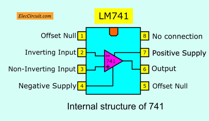
- Pin 1—Offset null
- Pin 2—Inverting input
- Pin 3—Non-Inverting input
- Pin 4—Negative Supply
- Pin 5—No connection
- Pin 6—Output
- Pin 7—Positive Supply
- Pin 8—Offset null
If you are a beginner. You like to learn many circuits. It is not fun to draw a real 741 on DIP-8 form. So, you should draw it with a 741 op-amp symbol.
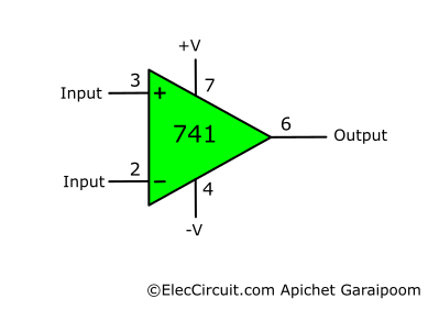
The power supply of op-amps
Most op-amp circuits use a dual polarity power supply. It runs well with a voltage supply of 4.5V to 18V
See in the image. Give a dual voltage with two 9 volt batteries. It is suitable for experiments. We can use the battery for long. Because the 741 is low power consumption.
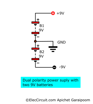
Then, see the image. Connect 741 op-amps to the 9V dual supply or split power supply. Positive, Negative of two 9 batteries.

Types of op-amps in use
741 op-amp is good in the amplifier. We can put into 3 types. Easy.
- Inverting amplifier—The input (+) connected to GND.
- Non-inverting amplifier—the input (-) connected to GND
- Differential amplifier—I often see in the power supply circuit as an error sensor. I will explain it to you later.
The Op-amp is suitable for error sensors
We can couple the op-amp directly and has a very high gain(typically 100,000).
This makes them very sensitive & ideal as error sensors. Because the sensing range for the op-amp is only about 100 micro-volts.
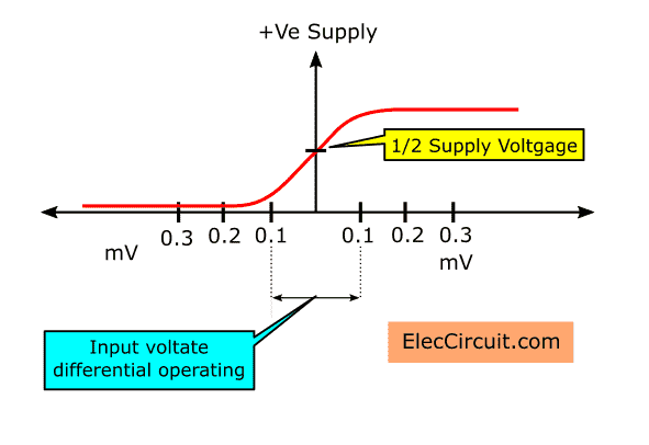
As shown in the graph below.
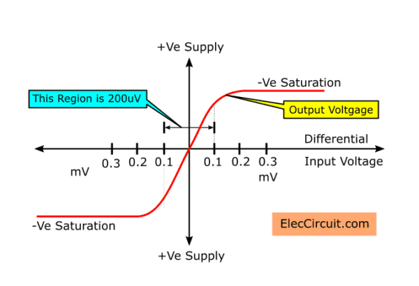
The following graph shows how the output voltage changes. It is according to the voltage on the two inputs.
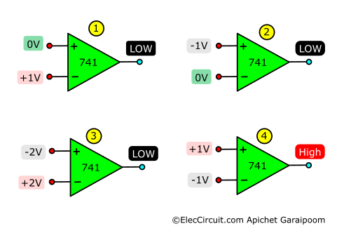
Look at In different states:
- The output will be zero:
If the difference between the two input voltage is zero, too. - As the voltage on the +input increase, the output goes high.
- If the -input into the same positive value, the output will fall to zero.
- And, the -input is negative the output will go minus.
- If the +input into the same negative value, the output will become zero (volts).
Do you understand? It’s okay if you are still confused.
Here are some examples:
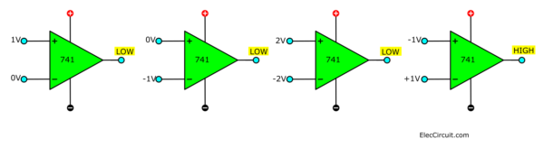
Did you fully understand the answers to the 4 examples on the previous?
If not, we will explain how the output changes according to the voltage on the inputs.
Op-amp swing output voltage
The 741 op-amp uses a split power supply.
Example +9V on pin7 and -9V on pin 4. With this type of supply, the output will go high: to 9V and Low” to -9V. It will swing 18V.
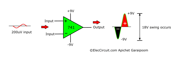
This 18V swing occurs when the input voltage changes 200uV. In this 200uV region, the op-amp is working in its linear range.
We can use the op-amp in its linear range on a power supply circuit. And, s very small change in the input will produce a large change in the output of the op-amp.
But the output can be positive or negative, according to the voltage on the input.
You must be able to determine the sign of the output. When the 741 is used as a comparator. (in the linear range).
In the linear region:
If the (+) input is helo within 200uV above the (-) input, the output will be a positive voltage. It is proportional to the difference between the two inputs.
Look at these examples show this:
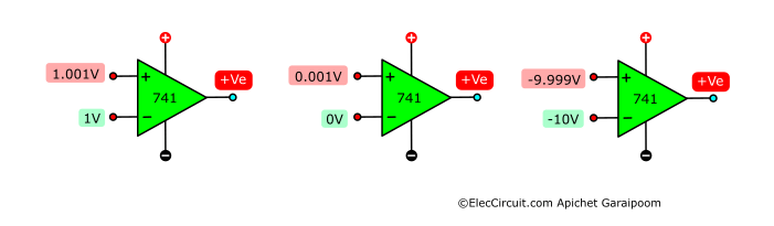
All outputs are positives.
If the (-) input within 200uV above the (+) input, the output will be a negative linear voltage. It is proportional to the difference between the input lines.
Do you get ideas? Look at 3 examples:
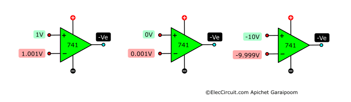
Summary
If the non-inverting input (+) has a higher voltage: The output will be positive.
If the inverting input (-) has a higher voltage: the output will be negative.
How to use it with a single power supply
The op-amp will also operate from a single power supply:
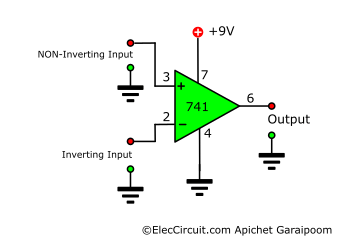
We will get the output waveform:
Note:
At zero difference between inputs, the output will be 0.5 of rail voltage.
The input voltage differential operating range is about 0.2 millivolts for full output swing. (about 200 microvolts)
Recommended: How to use op-amp in the power supply
Thanks to my teacher
Read others; Cr: Lean op-amp working as power supply on the Talking Electronics No.9 page 25 to 29
10 Example 741 circuits
I collect a lot of IC-741 circuits or tiny amplifiers using 741 op-amps as main. For use in various applications, In different ways.
The Clipping Amplifier Circuit
When an amplifier is overdrive output waveform of voltage and current distortion. it is limit size value.
This is the Clipping Amplifier Circuit using LM741(popular op-amp IC. It is a basic clipping amplifier. If the input is sine wave to distorted square wave type waveform.
Vout = -Vin(R2/R1) But the Vout not up to Vz+0.7V
The D1 and D2 are a Zener diode. If we use 6V values, have already the output voltage not exceed +/- 6.7V.
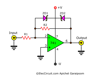
Basic Differentiator using LM741

Inverting Amplifier Circuit Using LM741
Friends at a study about the integrated circuit op-amp may nobody that strange Inverting Amplifier using LM741.
Today we come to see this circuit again. Reserve will valuable in applying work other circuits. Get in the future, we fix R1 and R2.
As a result, we will find the value Vout gets from a formula.
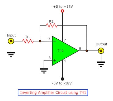
Vout = -Vin(R2/R1).
As a result request friends jubilantly with using integrated circuit using LM741
Non – Inverting Amplifier using LM741
This is Non – Inverting Amplifier Circuit by IC LM741.
For amplifier signal Frequency low power.
Today we try out Non – Inverting Amplifier circuit using LM741. Many people have who to ever study the integrated circuit op-amp may appear familiar good with this circuit.
It basically the base of the amplifier circuit. We can induce apply the work has very plentiful from our circuit has can calculate to find equipment value.
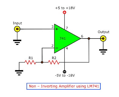
By appraising R1 and R2 control the expansion ratio has of the circuit as follows,
Vout = Vin(1+ R2/R1)
Request friends have fun Non – Inverting Amplifier Circuit by IC LM741,
Read also: Learn ON-OFF Light and Temperature Controller using 741 op-amp
Clipping Amplifier using LM741
When an amplifier is overdrive output waveform of voltage and current distortion. it is limit size value.
This is the Clipping Amplifier Circuit using LM741( popular op-amp IC). It is a basic clipping amplifier. If an input is sine wave to distorted square wave type waveform.
Vout = -Vin(R2/R1) But the Vout not up to Vz+0.7V
D1 and D2 are Zener Diode if use 6V values have already the pressure output not exceed +/- 6.7V.
Summing Amplifier using LM741
The summing amplifier is a handy circuit. It is a type of operational amplifier circuit and an inverting amplifier mode.
You can add several voltages of input together. More than two inputs can be used.
In circuit:
Vout = -R4 ((Vin1/R1) + (Vin2/R2))
When R1 = R2 .
Vout = – R4/R1 (Vin1+Vin2)
When R1 = R2 = R4 .
Vout = – Vin1 + Vin2
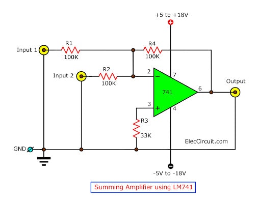
We seen the information in https://en.wikipedia.org/wiki/Summing_amplifier#Summing_amplifier .
An audio mixer circuit is another good example of the summing sounds from different channels together before, send the combined signal to next an amplifier circuit.
Basic Integrator using LM741
This is the basic integrator circuit used IC op-amp 741 is an important part. The following by ranges of input into the R1. It is Element Input and the C1 is the feedback element.
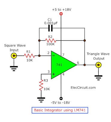
This circuit has a different form of differentiator circuit. The relationship of the incoming signal frequency. It has the effect of changes in voltage output as well.
So increased in parallel with R2 to control C1 (Low-Frequency Resistor).
When the frequency changes.When the frequency changes, and increased leg R3 Non-Inverting. To reduce the voltage Voi.
Read next: Universal Preamplifiers using | NE5532 | 741 | LM382
Single Polarity Supply circuit using LM741
This is a simple Single polarity (negative to positive polarity) power supply circuit.
For education, the work of a series op-amp. Since we use the input pin is a pin non-inverting. It is an important condition.
We try to come to see this circuit use op-amp IC LM741, be usable easily.
And, It can change R1, R2 for fix the expansion ratio has of the circuit with.
See the detail in the circuit.
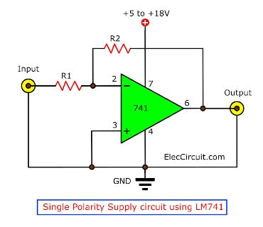
The input power must be negative only. As a result, the output voltage.
However, if the input is positive, it will not delete the output.
Because we used the power supply terminal positive and negative only.Or 4 pin connection with the ground.
This circuit may be adapted to the negative circuit. Or to converter a negative voltage to positive voltage.
The Buffer 741 Op-amp circuit
The buffer op-amp circuit. We use it for coupling two circuits together. Or the Unity Gain Follower Voltage Follower used to transfer or copy a voltage from a first circuit (Vin) to a second circuit (V out).
The input has a high impedance, and the output is low impedance. such as the differential family of the IC or transistor that’s not good impedance matching.
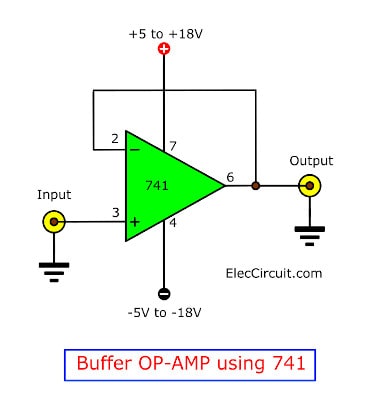
The op-amp IC objects have the output low impedance and input high impedance.
When connected to other circuits, so there is no effect. The gain is equal to 1 always. Does not to change any signal.
Vin = Vout
This circuit is an example of a buffer op-amp circuit, use IC Number LM741 performs this function very well, does not require any additional equipment.
We can use signals with any format, but the frequency response up to 1Mhz.
And limit the maximum voltage level power supply circuit is about 18V. This circuit voltage power supply is +/- 5V to 18V.
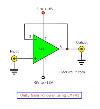
Unity Gain Follower using LM741
Musical Chime Generator Using UA741 oscillator
This is a musical generator that uses a bandpass filter circuit with ua741 op-amp as an act converts a sound signal in multiple feedback patterns.
When connected the voltage input from a rhythm generator with a short pulse, makes it ring in natural resonance frequency.
As the output oscillations vanish suddenly and resemble percussion or strum sounds natural.
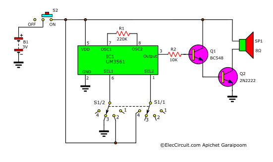
The higher the Q the longer the decay time constant. The VR1 is used to adjusts a Q value. The fo is 1/(185 x 1000 x C).
The high-frequency resonances resemble chimes, lower frequencies sound like calves or bongos.
Several circuits, all with different tuning, driven by pluses from a rhythm generator can produce an interesting pattern of sounds.
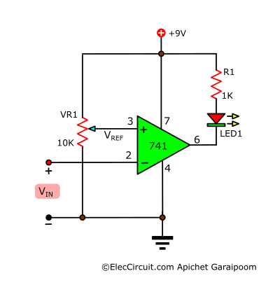
Simple level voltage detector circuit
Here are a few related posts you might want to read next:
- Automatic Night light circuit using LDR and IC-741
- Active bass booster circuit using 741
- Automatic Op-amp night light circuit using 741
GET UPDATE VIA EMAIL
I always try to make Electronics Learning Easy.
Related Posts

I love electronics. I have been learning about them through creating simple electronic circuits or small projects. And now I am also having my children do the same. Nevertheless, I hope you found the experiences we shared on this site useful and fulfilling.
Hi I would like to build voltage amplifier as weel as regulator using lm741. The input would be 0.05mv to 50volt. The input pulses per min would be 1-30000. The output pulse should be regulated 5 volt at all frequencies and voltage inputs. Plz if anyone could help me.