There is many how to make a simple touch switch circuit diagram. We can build them easily. Because of using basic components, transistor, UJT, and popular IC like 555 timer, 4011 CMOS, flip-flop IC.
We just touch the sensor lightly. Our bodies have resistance. It makes the current flow through the circuit is changed. The circuit will recognize and then turn off the electrical appliances.
There are 8 circuits diagrams list. You can choose the one you want.
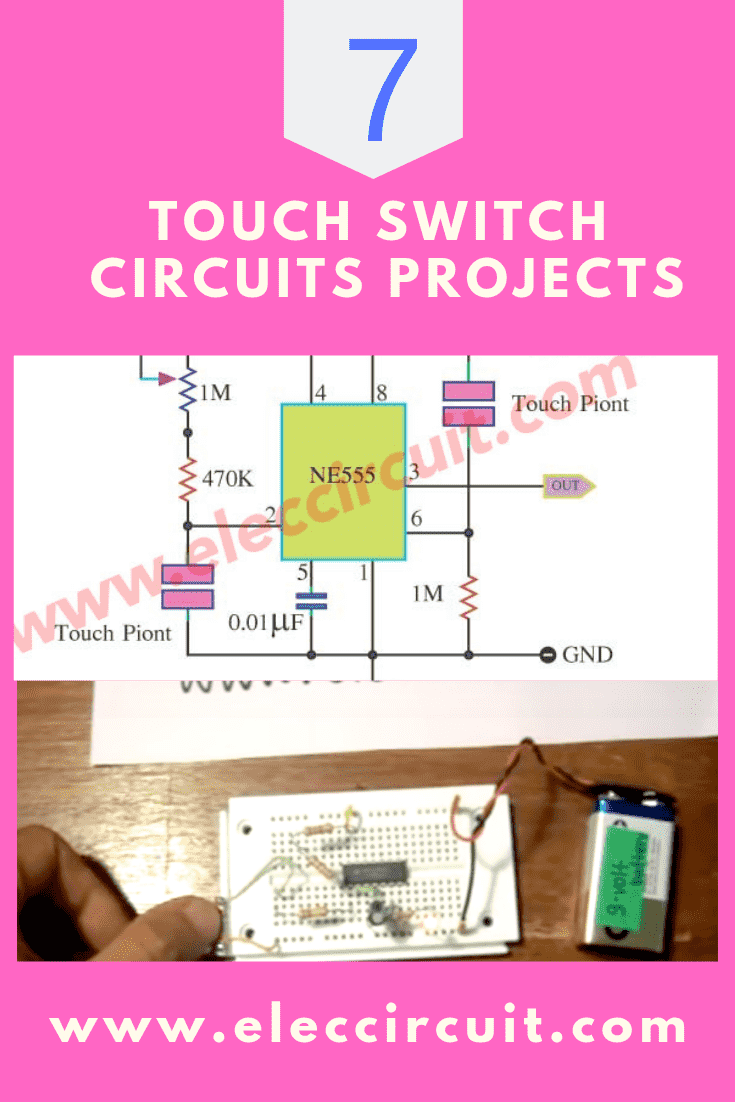
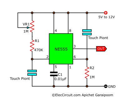
Touch switch circuit using 555 timer
This is a simple touch on and off switch circuit. It has a part compares with voltage 2 group. In-circuit uses an integrated circuit timer, LM555 or NE555.
Learn: How does NE555 timer circuit work
How it works
There are 2 touchpads for turn on and turn off to detect the change of voltage.
When we touch the first touchpad between pin 2 and ground. Our finger has resistance.
So, it passes the current (Hi) to ground. Then, at pin 2 is Low logic. It causes the IC-555 runs. Next, the high voltage goes out of pin 3 (the output).
After that, we touch off the touchpad is between pin 6 and a power supply voltage. The current flows through our finger to pin6. The logic changes to low voltage.
Also, the output switches to Low.
We can apply the output to control other circuits like LED, relay and input circuit.
Read below! You may be able to get more ideas about Touch Switch
Recommended: How does an SCR work
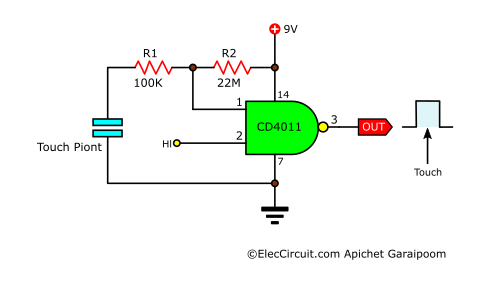
Touch toggle switch circuit using NAND gate
This circuit uses a 4011 logic gate digital as the bases of the touch switch. It is Standard and very easy because I used a Gate of IC 4011. In-circuit at pin 2 of 1/4 IC is Hi logic “HI” away.
If touching the plate connected to the 2 number. So the logic output is Hi, but don’t touch is Low logic.
The 22M resistor on pin 1 causes the circuit to be very sensitive to the touch.
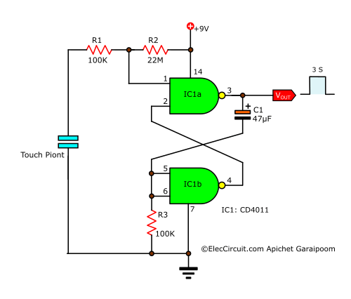
Touch Switch circuit project
Today we let to play a simple digital circuit. It is a One shot touch switch control. I use IC-4011 digital CMOS is base of a circuit. It is set to form as flip-flops. The Logic “HI” at an output when Your finger touchpad and is a time delay for 3 seconds.
Which we can determine this pulse time delay (one-shot) using the C1-electrolytic capacitor of 47uF (microfarad).
After that touching the plate connected, so well pulse output. Detail more Please read in this image circuit and see the video below.
In this circuit not have LED display, thus I add them in a breadboard, so that show working of this circuit. we use 1k-resistor is connected with series it to control proper current flow it.
Touch activated Switch circuit
This is a touch switch be simple again the circuit. It uses an integrated digital circuit is an important equipment, and use volt power supply low just 9V. By using single metal.
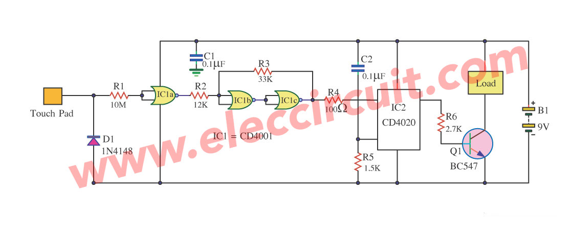
It works in the character turn ON and turn OFF. By when a touch for the first time turns ON, but enough for the second time turn OFF.
The circuit composes IC CD4001 to take an electric signal from a finger becomes the digital signal for change. The IC CD4020 be the counts two circuits or the divides circuit by two.
Subsequently, submit give the transistor drive Load next.
A Simple touch on and off switch circuit
If you want to make a simple circuit. This may be one of choice for you.
Simple touch switch using transistor
This Simple touch switch using a transistor is the touch switch is updated from the original version.
Which use IC to control the operation cause difficult for the electronics beginner. So this circuit is thought to are suitable because uses TR purely.
When was broken also a simple repair. and More cost-effective equipment. But The application is easy namely when we want to relay connected A and B contracts.
But when we want to relay release We also touch on the B and C.
The working principle
When we touch at point A and B will have some current from point B through our finger to point A.
Which base of Q2 this current will makes Q2 conduct current between pin C and E. This current will pass R-820 ohms into pin B of TR3 cause TR3 conduct current as well.
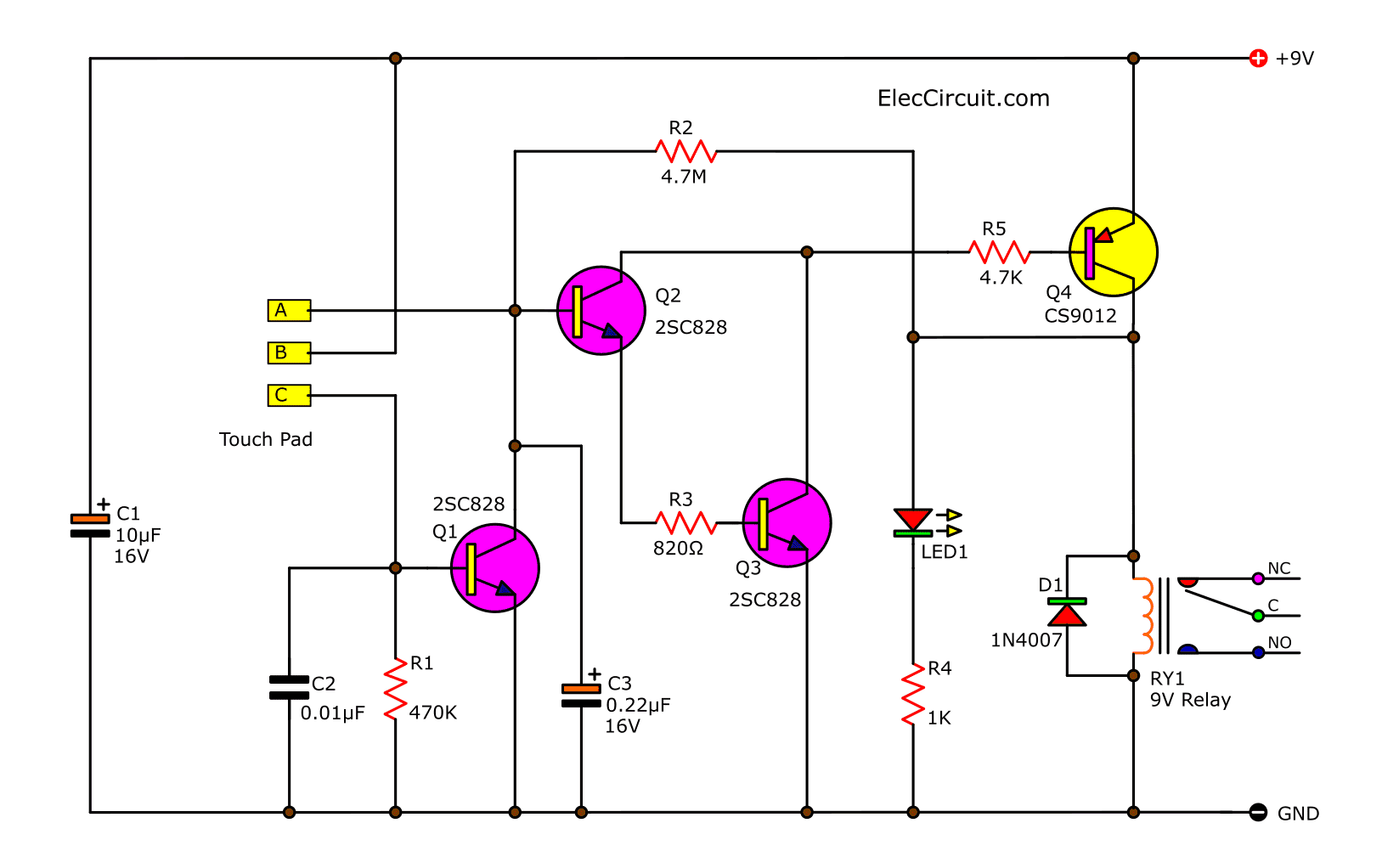
Figure 1 the cheap touch switch circuit using transistor
And this current will pass from pin BE of Q4. When Q4 has current flow through pin E-B will make it also conduct between pin E-C. Thus relay so derived the current and there is LED glow to indicate to we know once that the relay is running now.
While at pin C of Q4 will have higher voltage nearly equal this point voltage that through R 4.7M to pin B of Q2 cause current to flow continuously even we will release the touch point. The relay will remain active. When we want to make the relay stops working. We also touch points B and C. The some current will flow through our fingers from point B to point C.
And go to pin B of Q1, cause Q1 conduct, thus current pass through an R-4.7M instead will in pin B of Q2, Returned to the ground via pin CE of Q1, making Q2, Q3, Q4 not conduct current, stop conduct the relay so release contacts apart. Until the touches point new AB.
How to builds
This circuit uses the 9V power supply and all resistors use size 0.25W, Relay size 9V rate of the flow resistance of the relay depends on the needs of applications.
But usually, use the 1-3 A. D1 is for reverse voltage protection relay to the circuit. The C-10uF 16V makes supply voltage is smooth. and C-0.01uF, C-0.22uF prevents noise from the air that passes through the fingers when touched.
You can see the PCB layout in Figure 2. and the components layout as Figure 3 which if you are a lover of electronics will build it easily sure.
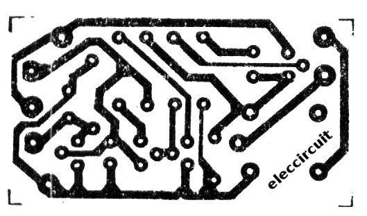
Figure 2 the PCB layout of cheap touch switch using transistor
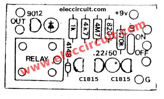
Figure 3 the components layout and wiring of the cheap touch switch.
The components list
Q1-Q3: C1815 or C828, 45V 100mA NPN Transistor
Q4: CS9012, 45V 800mA PNP Transistor
LED1: LED as you need
C-10uF 16V, Electrolytic capacitor
C-0.22uF 50V, Electrolytic capacitor
C-0.01uF 50V, Ceramic capacitors
0.25W Resistors, tolerance: 5%
R1-470K
R2-4.7M
R3-1K
R4-4.7K
RY-Relay 9V
Others components
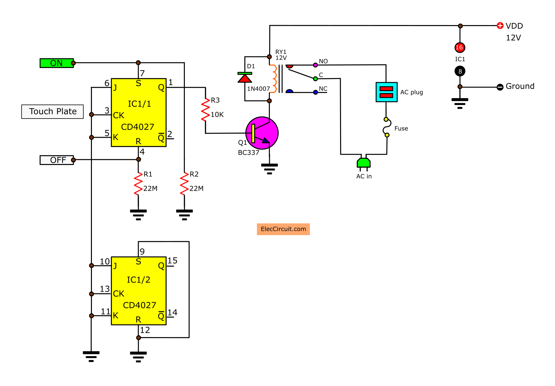
Touch plate switch circuit using UJT
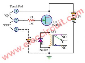
This is a very Simple Touch Switch Circuit. It used UJT 2N3819 is Main part numbers should set up this outside building circuit.
When staying far from the electric line or Power Line very much. Enough touch at in front touch 1 metal and 2 make Relay work ON getting.
When but urgent touch 2 metals only make Relay stop work OFF get. For within a building must enhance the part mends or in front touch 3 metals with following circuit picture.
The Relay use 6V to 9V sizes and Volt supply use 6V to 9V levels all right. Request friends have fun Touch Switch using UJT 2N3819
Touch Motor Controller circuit using SCR and Schmitt Trigger
This is a Touch Motor Controller circuit using SCR and Schmitt Trigger. It is designed to control 12V DC Motor. By using the touch on the plate, Motor as a result turn goes to once.
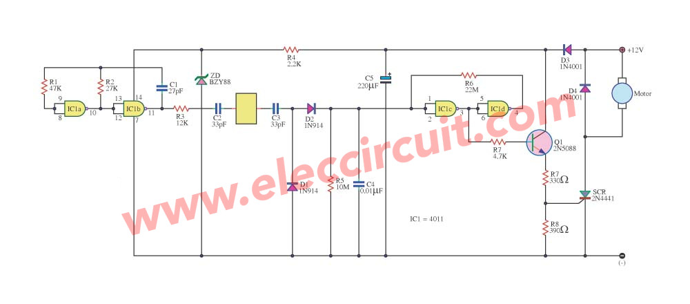
When using a finger touches the metal plate makes Schmitt Trigger Circuit (using IC-4011 NAND gate CMOS) take a signal from Oscillator Circuit and make a signal goes out to bias current a base of Q1-2N5088 works and then it will trigger an SCR1 to drive the DC Motor 12V then turn to follow want.
For the power supply type of DC Motor, this must be AC current 12 Volts Only. Because of make SCR not bias during negative current there.
And this circuit works not heavy DC motor power, turn? do not turn? Then don’t have to stick heat sink give SCR1-2N4441 for DC motor you will use the motor at use in an automobile all right.
GET UPDATE VIA EMAIL
I always try to make Electronics Learning Easy.
Related Posts

I love electronics. I have been learning about them through creating simple electronic circuits or small projects. And now I am also having my children do the same. Nevertheless, I hope you found the experiences we shared on this site useful and fulfilling.
i just need a circuit containing 3 relays with timer ic
Hi, you would need to be more specific about your question by stating exactly how your circuit should work, example, are the relays to be on one after the other with all staying on, or one after the other but this time only one stays on and the other goes off, or all at once? What function should the timer perform? I can go on and on with other questions. To save unnecessary typing, describe your circuit in full details, start with what voltage is to be used, what is the timing in seconds or minutes between trigger action or between on and off and so on, so we can help you.
Best regards.
Please give me detail info or name of reference books to make touch circuit by using IC555.
hi
I have a very good circuit watching all the circuits
Looking for a one touch switch that can cycle through 3 relays. Any suggestions?