Imagine you need to turn your lamps on and off every day. Is it convenient? But you can save time with this Automatic Night Light Switch Circuit. Before, I liked to use a transistor as the main component. But now, let’s try our hand at the Integrated Circuit (IC). In this Light sensor switch circuit using LDR and IC 741.
It is also very simple. In my opinion, it has higher sensitivity and greater accuracy than the transistor alternatives.
How Does Automatic Night Light Circuit Work
I called this project, in other words, a night switch circuit using LDR.
What is LDR? Light Dependent Resistor (or LDR for short) is a type of resistor, that changes its resistance depending on the light level detected. Or some people might call it a photoresistor. We usually use it in different types of optical detectors. Such as a light sensor, automatic light controller, etc.
In this circuit, we use the LDR as a light receiver from sunlight. And, changing its resistance to be applied to other components in the circuit as we need.
Read first for beginners: How do transistor circuits work
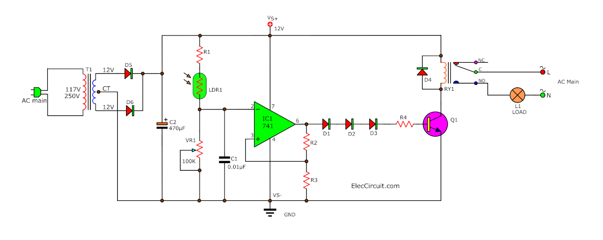
Now, let’s see the basics of the circuit. As Figure 1, a transistor Q1 will act as a switch, driving a relay, which is used to turn the load on and off.
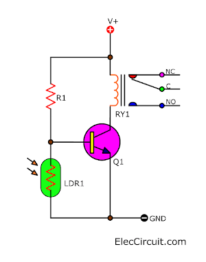
When the light hits the LDR, it will lower its resistance. This also lowers the bias current to the base of Q1. As a result, Q1 is not conducting current and cannot drive the relay coil. So, the relay cannot turn on the load.
Related: Making a Simple Light-activated relay circuit with PCB
But when there is no light, the LDR’s resistance will rise. This makes a biased current flow into the base of the transistor. Then, it conducts current to drive the relay, causing the lamp to turn on.
Transistor problems
There are issues worth noting, such as that when the light level is dim, the resistance of the LDR is rising. This causes the bias current at the Base of Q1 to rise, and the higher current flows through the Collector and the Emitter of Q1.
It makes the voltage across the coil of the relay increase gradually.
The relay will also create a small magnetic field. Causing the contact switch inside the relay to switch on and off rapidly, creating a spark. It will also generate a large amount of heat if the load uses a high current.
All of these will lower the relay’s life span, or at least cause us minor annoyance because the lamp rapidly turns on and off.
Recommended: Automatic night light circuit using SCR
In summary, the circuit above should not really be used. Because of the transistor’s indecisiveness in driving the relay at a certain time.
Instead of instantly turning on when the light level goes below some point and turning off when the light level reaches a certain point.
There are good solutions to this. See the circuit below.
How does the Schmitt Trigger circuit work?
We only need the status of the lamp to be on and off. Similar to how a digital signal only has “High” and “Low” or “1” and “0” states.
The issue is that the light levels detected by the LDR are quite diverse, ranging from very bright to completely dark. Causing the LDR’s resistance to change in response to the light level detected. Comparable to an analog signal. This resulted in the transistor misbehaving, as we talked about in the first circuit.
The said issue can easily be solved by converting the “analog signal” to a “digital signal”. There are several methods out there, but the most widely used one is the Schmitt trigger circuit, which we are going to use today.
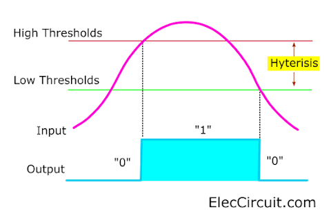
We will compare the resistance of the LDR to analog input. If the analog input starts to rise to the high thresholds, the output will switch to “1” immediately. But if the analog input starts to fall to the low thresholds, the output will switch to “0” immediately as well.
The gap between the first point and the second one is called a Hyterisis. The Schmitt Trigger circuit can be built with both a transistor and an OP-AMP. But now we have decided on the IC-741 OP-AMP. Because it has a higher efficiency than transistors, but the complexity and the price are a bit higher.
Here are a few related articles you may want to read:
- Understand these About xenon flash circuit Before It’s Too Late
- Simple remote control tester circuit
- Temperature detector circuit with buzzer alarm
Complete Circuit and OP-AMP Schmitt Trigger
I am quite unsure about how to explain the following content to be easy to understand. Because I think many of you readers would not like to read about some boring principles. So instead, let us learn about the practical part of the circuit in steps.
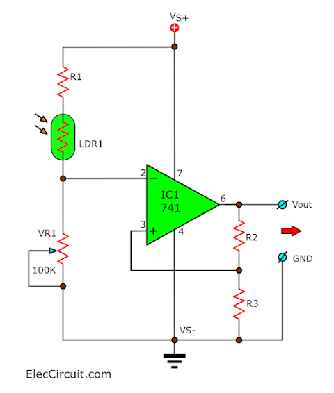
First, let’s take look at the light sensor section of the circuit.
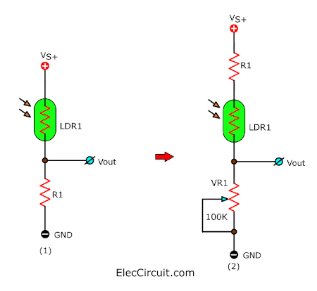
(1) From the transistor circuit above, we have switched the position of the LDR and the resistor. To increase the efficiency of the circuit.
(2) Later we replace R1 with VR1 to adjust the LDR’s light sensitivity and added R1 back in but now in series with LDR1 to limit the current into this part of the circuit. But they are still connected together as a voltage divider circuit as same as before.
Read next: Simple level voltage detector circuit using LM741
OP-AMP Schmitt Trigger Circuit
Next, let’s learn about the Schmitt trigger circuit using a 741 OP-AMP.
The five most important pins of IC 741
- Pin 7 is a positive supply (+12V).
- Pin 4 is a negative supply (GND).
- Pin 6 is the output of IC1.
- Pin 3 is a non-inverting input. This pin will receive a voltage, IC increases this voltage higher, then send it off to the output. If the input is low, the output will also be low and if the input is high, the output will also be high according to the ratio of the input.
- Pin 2 is an inverting input. If this pin receives a low voltage, the output will be a high voltage. But if this pin receives a high voltage, the output will be low voltage. The output voltage will always be the opposite to the input voltage of this pin.
Suppose that it is daytime, and there is a light hitting LDR1, causing LDR1 resistance to drop and the voltage across VR1 to rise.
At the same time, the voltage at pin 2 of IC1 is also high voltage. But the IC’s output (pin 6) is in a low state.
All of this causes the voltage across R3 to also be reduced. This voltage is then fed back into pin 3 of the IC. This resulted in the output voltage (pin 6) being even lower.
This cycle will continue until it reaches its lowest point, at which point it will stop and the voltage will stay at that point. According to my experience, this voltage will sit at around 1.8V to 2.2V. Because we supply only a positive voltage power supply to IC1. Making a low state of the output cannot be 0V.
This amount of voltage can make a transistor misinterpret it as a high state, causing it to drive a relay during the daytime. We did not want the transistor to do so.
Recommended: Learning electronics for beginners
Diodes Regulator
But it can be solved by putting in three diodes (D1-D3) in series. Three of them have a total voltage drop across about 1.8V (0.6V+0.6V+0.6V) at both high and low states.
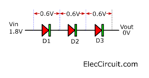
They will take those voltages for themselves, causing zero voltage at the Base of a transistor. So, the transistor would not drive a relay, as we have wanted.
On the other hand, when the sun goes down and there is no light hitting LDR1, causing LDR1 resistance rises and the voltage across VR1 reduces.
At the same time, the voltage at pin 2 of IC1 is also low.
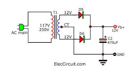
It causes the IC’s output to be in a high state and also makes the voltage across R3 rise. Pin 3 of IC1 has an increase in voltage as well. This resulted in the output voltage going up even higher. The cycle will continue until it stabilizes at around 11V when using this 12V power supply circuit, which consists of T1, D5, D6, and C2.
But this output voltage passes through three diodes (D1-D3), reducing the voltage by 2V. Leaving only 9V for the relay driving circuit, which is enough for it.
Relay Driving Circuit
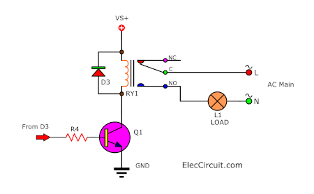
First, the current got reduced by R4 and then passed to the Base of the transistor. Biasing the transistor so it can let the power supply voltage flow through the coil of the relay. Causing the contact switch inside the relay to turn on and letting AC main flow to a load or external lamp glow.
We use the D4 to prevent reverse voltage from the coil of the relay so as not to harm Q1 or other components.
- Light Sensor Switch Circuit using LDR and 741 IC
- How to Build a Night Light Circuit with an LM741 Op Amp
- Recommended: SCR circuit diagram
Complete Circuit
Now we combine all of the circuits from above together. And we will get a working Automatic Night Light circuit; the only thing left is the lamp as a load. But after a bit of testing, the circuit was too unstable. To solve this, I have added one capacitor at the input (pin 2) of IC1 to help decrease noise and spike signals.
Read Also: Learn ON-OFF Light and Temperature Controller using 741 op-amp
Build and Setup Guide
Since this circuit has quite a few components, we recommend building it on a perforated board or universal board.
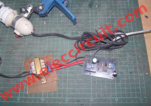
If you would like to save money use may use a cheap 12V AC adapter instead of the 12V power supply circuit used in the complete circuit above.
The LDR should be covered with a small tube. To prevent unwanted light.
If you want to change the light sensitivity of the circuit, it can be done easily by adjusting VR1.
Watch the video below for the tuning and testing process of this circuit.
Components lists
0.25W Resistors, tolerance: 5%
R1, R3: 100K
R2: 330K
R4: 4.7K
Capacitors
C1: 0.01uF 50V Ceramic capacitors = 1 pcs.
C2: 470 uF 16V Electrolytic capacitors = 1 pcs.
Semiconductors
D1-D3: 1N4148 or 1N914, 0.75A 200V Diode = 1 pcs.
D4-D6: 1N4007, 1A 100V Diode = 1 pcs.
IC1: LM741, 8 DIP, OP-Amp IC = 1 pcs.
Q1: BC337 or BC549, NPN transistor = 1 pcs.
Others
LDR1: Photoresistor
VR1: 100K, Potentiometer = 1 pcs.
RY1: Relay contact 12VDC
T1: Transformer 220V output 12-CT-12V, 100mA = 1 pcs.
PCB Universal, Plastic box, Wires, Socket IC 8 pin.
Also check out these related articles:
- Light Actuated Relay Circuit using Photo Transistor
- Automatic Night LED light switch circuit using solar rechargeable
- How to make automatic daylight sensor switch Project
Download This
All full-size images and PDFs of this post are in this Ebook below. Please support me. 🙂
GET UPDATE VIA EMAIL
I always try to make Electronics Learning Easy.
Related Posts


I love electronics. I have been learning about them through creating simple electronic circuits or small projects. And now I am also having my children do the same. Nevertheless, I hope you found the experiences we shared on this site useful and fulfilling.
Sir,
I have been watching….looking….and build some of your projects be it I am an Electronic Technician your circuits are AMAZING I know somehow I guess they are old circuits but I admire you for the time you spend publishing all the circuits believe me, I HAVE ALL YOUR CIRCUITS ON A DATA BANK permanently and constantly look if I need to build something small so once again, I respect you and your circuits great and a big thanks.
741 in 3 ile 7. bacağı arasına 100 K direnç bağlanmalı
so good
Hi baraka.
Thanks for your feedback.
Man this is so interesting i haven’t open circuits like these so easy to construct. but i wl’d love seeing its board connection layout cause a not all that an expert.. thanx
really loved it.But just a suggestion R5 should be 47k instead of 4.7k cause I made it to work when I used 47 k.
What IC did you use? Is it UA741 or LM741? I used LM741 but it did’nt work.
Yes you are right, I used 47k and UA741 and it worked very good, thanks.
There is no resistor 5, where is it?
Hi,
There is no R5. We have already updated it.
Thank you for your patience and interest in this circuit. 🙂
i would like to know, how to connect the potentiometer
Sir can you tell me about the relay connection and how it’s work ?
hello sir, can i use smd component ?