Automatically change the dark corner of the house to be brighter. This is an automatic night light circuit system with an LED display. No AC main but can run with battery solar charger. Do not doubt that How does it work or is it easy?
Learn more.
Because of some houses are not a convenient plug. So the charging system with a solar cell.
Moderately convenient to use.
At night, the LED lights up and LED daytime off. With electricity from solar cells charged a 12-volts battery.
Are you ready? Let’s get starts.
Recommended: SCR circuit diagram
Guidelines circuit design
We need Lamps automatically lit up when dark or night.
But the place that installs them. No AC electrical cable. So I use battery 12-volts as a DC source. Which is suitable for LED lamps.
I use LED 12-volts 1.5-watts as Figure 1. It uses a low power consumption than the general lamps.
And also a long life (20,000 hours up). But expensive price than general about 2 times.
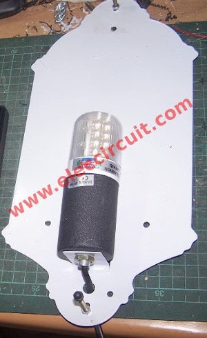
Figure 1: LED Lamp 12V 1.5W
But the battery requires a DC charger circuit, too. Which we would to like use solar cells. Because easy to use in a location that has sunlight. To convert as DC voltage between 17 volts to 22 volts at 10 watts per one unit.
Read next: Automatic night light circuit using SCR
Look at Figure 2: the solar cells that we use. I get them from great my friend. Though very ancient but it still is helpful.
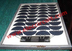
Figure 2: Solar cells as source charger
How it works
In case of this automatic LED night light switch, we should save energy so I design this with main parts below:
- LDR or photoresistor is used for sensor light-activated. It is cheap and easy to use.
- A CMOS Digital-IC No.CD4069 is a inverter gate every useful and cheap.
Simple Night Light Sensor circuit
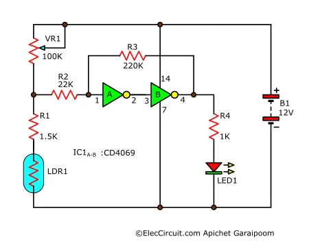
Next, we will design a simplified night light sensor as Figure 3. Here is a step-by-step process:
First, The 12V flows through VR1(potentiometer) to LDR1(photoresistor) and R1.
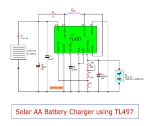
Recommend: Simple 1.2V AA battery Solar charger circuit
Second, an LED1 will glow brightly. Or when LDR1 gets that no light or night status.
Now, its resistance is high. So, cause a voltage drop across both LDR1 and R1 are high state or “1”, too.
We will see that R1 connects with LDR1 in series. To limit the current through them not too much.
Then, look at An IC1a, IC1b, R2, R3 are assembled together as a buffer gate. They work similarly to the Schmitt triggers form (we will see detail later).
Next, the output of IC1b pin 4 is logic high that voltage of 12-volts. It causes LED1 glow and R4 reduce properly current for LED1.
Here are a few related posts you may find helpful, too:
Buffer Gate And transistor Driver
Anyway, as the requirements of the circuit. We should add “third” is using the transistor instead of a relay. Because the transistor driver uses a lower current than the relay.
You can see in Figure 4. Q1 and Q2 are connected in a Darlington compound, very many gains. The Q2(TIP31) can use lower than 2A. So use easily with 12-volts LED lamp 1.5 watts or 0.125A current.
Also, IC1c and IC1d, IC1e, IC1f are mixed as buffer gates. They are simple current amplifiers. To increasing current up before to transistor driver.
We use IC1 fully 6 inverter packets. It’s worth it
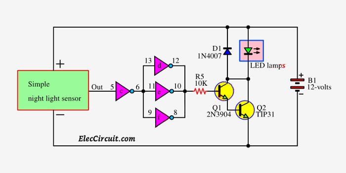
Figure 4: Buffer Gate And transistor Driver
After that, look at some components working:
- C1-220uF 25V electrolyte capacitor for filter smooth current
- C2-0.1uF 50V – ceramic capacitor as spike remover of IC1-digital IC.
- D4-diode-1N4007 is used to absorbs the current spike from LED lamps to protects external transistor drivers and buffer CMOS gate circuits.
The complete circuit diagram
Then, we see Figure 5 the complete circuit. We add the solar cells charger circuit for a 12-volts 2.5Ah battery as a power source of this circuit.
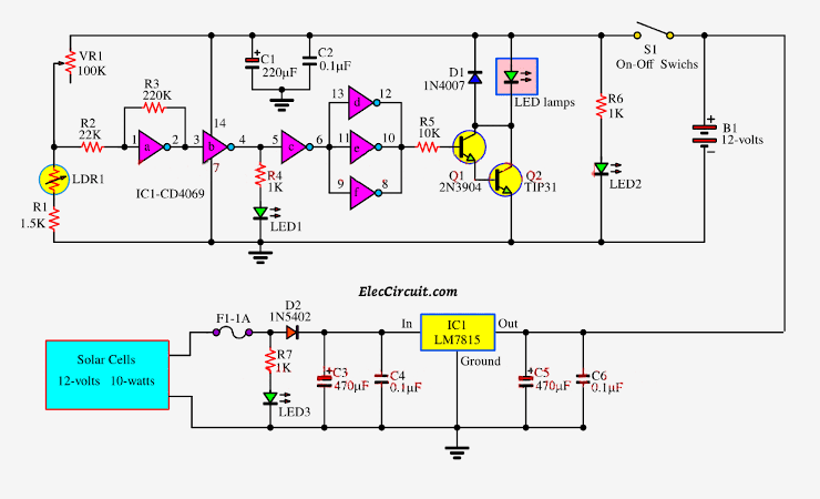
Figure 5: complete circuit
Here is a step-by-step working:
The battery can power a long time for 2.5A/0.125A: 20 hours. Which normally we need to use it for 8 hours per night only. Therefore it can be used easily.
Because of the output voltage range of solar cells between 17V to 22V. So, we use the LM7815 DC voltage regulation output to 15-volts. Or 1.5 times of voltage battery.
D1-1N4007-diode protects voltage feedback from the charger circuit.
Both capacitors C3 and C5-470uF 35V filters a voltage to the best smooth. And C4, C6 filter noise, too.
LED3 for indicating voltage solar cells and R7 controlled current-limiting of LED3.
The solar charger circuit directly connects to the battery. And S1-Switch is used for turn ON-OFF this circuit.
LED2 shows power on, and R6 for current-limiting.
LED1 indicated the circuit of the light sensor section.
Related: Outdoor solar lights circuits
How to build and test
This project, we assemble parts on a perforated PCB. And, wiring to universal PCB board.
Look at: Figure 6
Then, test it as shown in the video below.
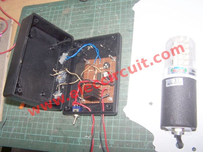
Figure 6: Assemble parts on perforated PCB
Testing circuit.
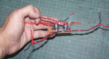
Then, assemble a simple solar charger circuit as Figure 7
Check out these related articles, too:
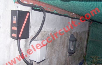
Look at Figure 8# this is tnstalling this project in a real place.
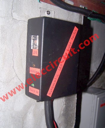
Here is Figture 9: The automatically night light controller
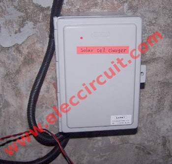
See Figure 10: Front of solar cell charger box.
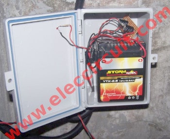
In Figure 11 show inside the solar charger box
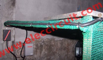
Figure 12: Use Corrugated Cable Conduit for wiring outdoor successfully.
Application
This project is easy but you should solar-cells at sunlight all day and use big size or high power more than 10 watts up.
On the first day, it may not fully work. You wait it comes to the third day it will good running.
Two weeks ago this project works so well. Everyone in my family likes it. I think it will have a long life and save money too.
The component list
Q1: 2N3904, 45V 100mA NPN Transistor
Q2: TIP31, 30V 2A NPN transistor
IC1: CD4069___Six inverter CMOS
IC2: LM7815, 15-volts DC Regulator IC
LDR1: LDR or Photoresistor
Electrolytic_capacitor
C1: 220uF 35V
C3,C5: 470uF 35V
Ceramic Capacitor
C2,C4,C6: 0.1uF 50V
0.25W Resistors, tolerance: 5%
R1, R7: 1.5K
R2: 22K
R3: 220K
R5: 10K
R4, R6: 1K
VR1: 100K, Variable resistor or potentiometer
Perforated board
Box,wires,solar cells,LED lamp 12V,and others.
- Not only that. You should read: Automatic Solar Night Light Circuit Project
It is so easy and good learning for all.

I love electronics. I have been learning about them through creating simple electronic circuits or small projects. And now I am also having my children do the same. Nevertheless, I hope you found the experiences we shared on this site useful and fulfilling.

thanks for your help for am new in electronics
I want to make a inverter of approx. 1000w.
so pls. send a circuit diagram with component list.
thanks with regards
sunil pandey
Hi Admin
Can I use This solar cell with the voltage regulator IC LM7815 circuit as source with https://www.eleccircuit.com/220-volts-power-inverter-using-ne555-and-mosfet/
this circuit. I just want to use above circuit instead of the battery and the else circuit.
Is it Possible Pls Reply…
Thanks…
dist -junagadh .
respacted sir ,i requarment led auto cut lamp ,so please help me this product ,(i purchase this products .)
thanks ,i awayting your positive reaply.
1.can i use a 12v 5A power supply to replace the solar cell?
2. Will it automatically charge the battery when its drain?
Hello. You are doing great job here, congradulations.
I don’t know much about circuits but I have a few questions on your “Automatic led night light switch” project.
– At the beginning you mention C1 as 220uF 25V but on your parts list it is listed as 35V. ?
– You are using an LDR circuit to detect darkness. Couldn’t you use the solar cell itself for this purpose. It would not produce electricity when it is dark and thus isn’t it a sort of light sensor?
– how could we adopt this circuit for 6V battery and 6V LEDs?
Thanks
Thanks for doing this
Nice
Thanks for your feedback.