This is a really Simple level voltage detector circuit. I like it so much because it causes me to know the principle of the comparator circuit form.
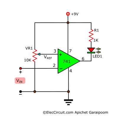
As shown in Figure below, We use the LM741 OP-AMP circuit highly popular is the base of a circuit.
Testing
As the video below. When we set all components to breadboard successfully. Suppose, we want to detect a voltage of 2-volts.
Here is a step-by-step process:
- First the circuit without any errors.
- Apply a 9-volt power supply to the circuit.
- Rotate or adjust a VR1-potentiometer in the breadboard to set a reference voltage to pin 3 (read digital multimeter in left is 2-volts).
- Apply an input voltage to the INPUT at pin 2 of IC1(Read voltage as Zero).
- Now LED goes out.
- And Measure output voltage equals the power supply voltage 8.4V approximately.
Then, I increase the voltage at pin 2 continuously until to 2-volts as volts multimeter. It makes the LED1 glow immediately.
Although we still add voltage up many voltages.
While measures the voltage at an output as 2-volts. It is lower than the positive (9V power supply) voltage.
So LED glow.
You may also like these:
Therefore, When voltage at pin 2 larger than pin 3 cause output pin 6 as low voltage when compare with ground so LED light up.
The resistor-1K is used to control the current to LED1.
3 Others circuit using 741 voltage comparator
1. Simple temperature sensor diode 1N4148

Learn how to use a diode to sensor temperature. The voltage across the diode gets slightly different voltages. We can use 741 op-amps check it easily.
Read more:
2. Car overheat alarm circuit
We apply Thermistor for this circuit. It is a better diode. Also, we use 741 op-amps as a comparator circuit.
Read more
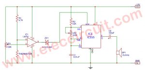
3. Automatic Op-amp night light circuit

Also, this circuit we use 741 op-amps to detect a level voltage across a voltage divider. They include LDR and potentiometer.
The event above circuits is old. But now they are still working. Of course, you can learn Electronics with them.
GET UPDATE VIA EMAIL
I always try to make Electronics Learning Easy.
Related Posts


I love electronics. I have been learning about them through creating simple electronic circuits or small projects. And now I am also having my children do the same. Nevertheless, I hope you found the experiences we shared on this site useful and fulfilling.
Have a circuit that comes from the dash info center of my Dodge Diesel, it is the low fuel level reminder light driver. It appears to be an Op amp( 8 pin ) and a power transistor. Neither of these parts have #’s which I have been able to use to identify them with. The light will not go off no matter how much fuel is in tank. The circuit is no longer replaceable from the Dealer as it is too old a model. IC # is CB9047n — Transistor # is simply 6209 thought possibly this # might be a Vreg. The circuit has a lot of components just to be a driver such as a voltage to current converter which is what I surmise. There are only 4 connections to the board, so 1 has to be V+, 1 v-, 1 going to the light, and 1 coming from the gauge sending unit, which has 3 wires to it, +,- and the signal wire which is a variable voltage. If the parts can be identified, I would use a replacement of similar value and rebuild the board. If not I must make a new board that will do the same job, turn on the filament lamp when the signal from the sensor reaches a set V. and turn off when the V is out of low limit range. I have some ideas on how this should be done, but starting over from scratch will be more work then simply repairing the original circuit. Got any suggestions?
find that the op amp is a dual so it will not be difficult to replace this if the part does not a critical spec sheet,which I doubt it does. So it looks like I’ on the way to getting it figured out. Still welcome any info or suggestions.
Does this circuit only work on sensing a DC voltage or will it also work on an AC (audio) signal – for example to confirm that the amplitude is correct?
Yes, in theory, it can sense AC Audio signals with just a few adjustments to the circuit. But we have not tested it yet, so it might be a waste of your time or even a risk of circuit errors.
Anyway, this circuit is still interesting, maybe in the future, we (I & my daughter) will experiment with this circuit.
Please stay tuned.
This could be answer to what I need.
The cct you give runs on 9V ….. I need to use 12V, as a 741 will works up to 22V is the only change needed to get correct resistor value for R1 to suit LED
R = (Vs-Vf)/If
Hello, Rick Hughes
Thanks for feedback. The 741 chip is normal op-amp. You may try LF351 it is better one.
If you use it for detect voltage I think you may use LM339: https://www.eleccircuit.com/low-voltage-battery-indicator-circuit/
Thanks