This is complete stereo amplifier circuit 60W +60 W without customization. Which is easy to build , sound quality, and cheap because the LM3876 works perfectly.
Now. IC amplifier is very popular. Therefore has components manufacturers produce and distribution IC such as STK, TDA, and LM greatly. And often are used in Mini component and easy to build, saving, fast.
Due to the complicated circuitry is contained within the IC is complete. Therefore does not require customization. Just a small number of external components, can use it.
In this project we choose to apply a LM3876 of National Semiconductor Company. provided power up to 60 watts at load 8 ohms. Which is a size is great for listening in the room. Within this IC is packaged various many protection circuit.(Safe Operating Area: SOA) such as Protection signal spikes from power supply. protection short output to ground or power supply Temperature control circuit inside the IC. The protection circuit Transient signal to output, Over voltage protection circuit, the voltage drop or overload. This IC is resistant to all conditions. Therefore to try to make them more active.
The working of principle
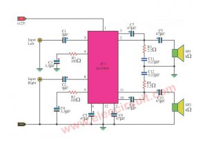
From the Figure 1 is shown only one amplifier channel. Because the other channel is the same everything. That IC1 will be served full option inside it. Just have little more circuit only. In the power supply section, The output network before connect the speaker, a fuse protect a spike voltage and each external components has served as follows.
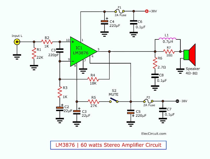
Figure 1 the complete 60 watt amplifier stereo without customization.
– The sound signal to an input of circuit will pass RC networks that include R2 and C1 protected disturbance of radio signals. And reduce the RF signal to lower before the signal will in to pin 10 of IC1, which is connected as non inverterting amplifier that gain rate fo 19 times.
This gain coming from feed back at input through R4-resistor and R3. Calculated from the formula (1 + R4/R3) there. For C2 that connects with R3 will reduce lower frequency to -3dB at 7 Hz.
The audio signal is amplified successfully will out of pin 3 of IC1. But before this signal to the speaker there will must through a zaobel Network circuit that consisting of R6 and C8. To solve the problem that is driving the load capacity. and maintain, stabilization on high frequency by RL network with use coil about 0.7 uH turn on resistor 10 ohms 1 watts (Parallel) protect changing of impedance of load changes on have high frequency to output. to high qulity of sound that to clean and clear all sound frequencies range.
This S2 is a switch control a working of a mute circuit inside IC1. This circuit type has Special features that usually come with amplifier IC already. In this circuit, if S2 close circuit then normal sound out of the speaker. But when S2 open circuit, cause do not connect circuit will making lower sound about 110 dB sound that out of the speaker so very weak. The capacitor-C3 that connect with pin 8 of IC1, will cause partially increase sound to normal level. After that S2 come back to close circuit again. To protect spikes sound out of speaker.
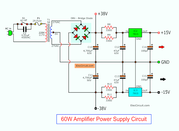
38V and 15V Dual Power supply circuit, for pre amplifier too
In the power supply will has C9-capacitor that connected the switch-S1 to No thumping sound output speaker. While opening sound. Then a transformer-T1 will reducing voltage size down to 27-0-27 volts AC current 4 Amperes. Then through BD1 to changes into DC about +-38 volts. By there are C10 and C11 filter voltage to smoothly. To as voltage supply of the amplifier. And then unless also is designed for the audio tone control circuit are the voltage +-38V will reduced lower voltage by R8-R11 to protect voltage across IC2 and IC3 too much, the voltage will reduce lower to through the regulated circuit to +15 volts, by IC2-LM7815 will be positive voltage of 15 Volts and IC3 is 15V negative voltage.
You may also like these:
How to builds
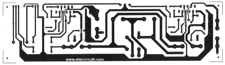
The building is easily this projects, before make the PCB as same real size in Figure 2. Then put all components in the PCB as Figure 3.
Figure 2 the PCB layout of 60W stereo amplifiers without customization
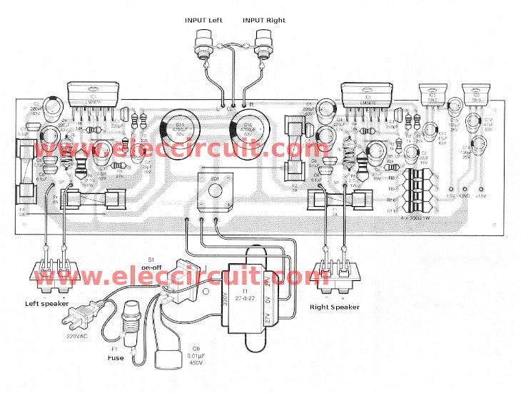
Figure 3 the components layout of this projects.
Positions of switch S2 is the mute circuit. If who think unnecessary, to solder directly to each other. But the prototype is soldered together. With a jumper wire under R4. They IC1, IC2, IC3 must install the heat sink to tansfer heat out of the IC. Once the installation is complete, measure the body of IC1 (LM3876) that Short with a heat sink or not. Because Short, may cause damage to the power supply and IC1.
The making RL-network at output of circuit before connect to speaker. First, uses a copper wire diameter 0.4 mm length about 12 inch. turn around with resistor 10 ohms 1 watts of 10 times. as Figure 4 Soldered copper wire in the leg of the resistor.

Figure 4 how to build RL-netork
Testing voltage and current before application
Although this projects without customization. But must to check voltage and current before use. To prevent damage to the device.
The first stage of the checking. Without the fuse to PCB includes a signal input and speaker. Next, measure the power supply circuit see that about +-38V. And then check current flowing in circuit. By bring the multimeter set to current range measure at fuse socket in PCB ( measure across fuse) The current that measure will be must under 70mA. Measure like this the position of F1 and F2. Then put two fuse F1 and F2 successfully.
GET UPDATE VIA EMAIL
I always try to make Electronics Learning Easy.
Related Posts

I love electronics. I have been learning about them through creating simple electronic circuits or small projects. And now I am also having my children do the same. Nevertheless, I hope you found the experiences we shared on this site useful and fulfilling.
Dear Sirs,
I am so glad to see the type of circuits that you publish regularly. I am a hobbyist who has retired and now has some time on his hands to indulge in Electronics.
While thanking you, please let me know if there is any way I can assist you in this program. I am not an engineer, just a ordinary person who enjoys the subject.
Thank you,
ivor
Dear Sir,
I so glad to see various projects and circuits shown in your website that i am surfing this website for the first time and cant stop myself to comment on the website.
any body beginner or the expert can make easily projects….
the most wonderful thing about the website is that all the content available is free. Students in school can take help from this site… i will suggest to all the students to use your website.
I am highly thankful to you to send me your new projects on my E.mailing address.
What can I so for you in return?
I am waiting for your kind reply.
THQNK YOU
Sincerely
A.N DHAREJO
I am highly thankful to you to send me your new projects on my E.mailing address.
What can I so for you in return?
I am waiting for your kind reply.
THANK YOU
Sincerely
A.N DHAREJO
Please can any one make PCB for me
Hello,
I would like to realize a compact station: preamplifier, equalizer, power amplificaor from this schema.Se can show me the rest of the schemes.
One more question.
We have seen that the power output stage is + / – 38 V and source presented is + / – 15v.
Best,
Vasile
Sir ihave 6inch 40watt boofer and i want to best audir circuit for dolby sound
No matter how much big the balls grow, it always stays beneath the dick
Hello, where is the list of components?
Hi oskars,
Thanks for your feedback.
Now we not have list of components, sorry.
Sir what should i do to this spare -+15v?
where is the tone controlo for this?
Hi dear sir and everybody there ,
my question is just like of bonnie , vasile & other friends . the 2 head of + & – 15 v .
is there an interface for its or this is a half of schematic diagram ?
please do me a favour and tell us some words for better understanding
because i’m interested of make it very much .
you know , in fact i’v bought the majority of things plus pcb
with my respects amir
Good
Hi ubiran braga.
Thanks for your feedback
hi dear sir
i finally take & arrested it . not bad , but not strong enough that you had wroth about .
please tell me if i’m in wrong way , i think about increasing the gain until 30 by
changing value of R3 to 560 ohm . what is your opinion sir ? is it will be ok ?
your help is highly appreciated.
thanks in advance .