If you are looking for a good IR receiver circuit or infrared receiver project. This post is one choice that should be read. It is suitable for Remote control and more circuits.
Which you can do it in two ways: a simple version and the special infrared receiver circuit for you.
Both circuits have a PCB layout. Moreover, you can buy all parts at a local store near you.
Simple infrared receiver
This is a simple infrared receiver for the burglar alarm system or the other protection, etc. It has a few components. There are the most common transistors and photodiode to receive an infrared signal( with an Infrared transmitter using 555).
Let’s build the Infrared receiver circuits. Which we have many circuits.
To begin with, the simple circuit as Fig below.
We will see that a photodiode connects in the reverse bias form. So, while the infrared light into it. It has very little current through it.
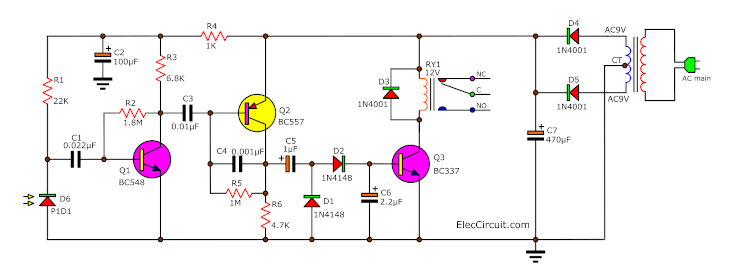
The simple Infrared receiver circuit diagram
But when the infrared light reaches photodiode PD1. It will cause the current to flow through the diode is good.
Next, it causes a voltage signal that changes according to the frequency of the signal transmitter to transistor Q1. It connects with Q2(BC557). They are in an amplifier circuit form with gain about 1000 times.
Others components:
Both capacitors C2 and C3 are the high pass filter circuit. While both diodes D2 and D3(1N4148) act the convert AC voltage signal to DC Voltage. Then, C5 will filter the current to smooth.
Last, The output voltage drives the transistor-Q3 to the relay works. The relay so works when has the infrared light from the transmitter to the receiver.
If this infrared beam is cut or obscured. The relay will stop working. This circuit is suitable for use in the burglar alarm system or other protection, etc.
Build a simple IR receiver circuit
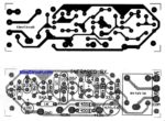
Figure 2 the PCB layout and components layout of the simple infrared receiver
We should make the PCB layout as Figure 2. Because the high-frequency receiver from photodiode as low current. So, it may be much noises.
Component list
Q1: BC549, 45V 100mA NPN Transistor
Q2: BC557, 45V 100mA PNP Transistor
RY1: Relay 12V coil
D1, D2: 1N4148, 75V 150mA Diodes
D6: Photodiode
D5,D6: 1N4001, 1A 50V Diodes
Ceramic Capacitors
C1: 0.022uF 50V
C3: 0.01uF 50V
Electrolytic Capacitors
C2: 100uF 25V
C6: 2.2uF 25V
C7: 470uF 25V
0.25W Resistors, tolerance: 5%
R1: 22K
R2: 1.8M
R3: 6.8K
R4: 1K
R5: 1M
R6: 4.7K
Simple remote control tester circuit
I am going to show you a simple remote control tester circuit. When the remote control is broken. We cannot use it. First, we should check the battery. If the battery is good.
The remote circuit may be a problem. We cannot check it with a normal tool, a multimeter.
This simple remote control tester circuit may help you. It can read an infrared light of remote control.
How it works
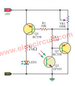
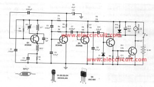
This circuit acts like the infrared receiver of electrical appliances. Because the human eye cannot see infrared light. But a phototransistor can detect infrared light.
In this Simple remote control tester circuit. So we use the phototransistor as the light receiver from the remote control.
If it is good. The phototransistor-Q1 will get the infrared light, the current flows through it to the base of Q2(PNP transistor BC558).
It switches on. the current from the ground can flow through R1 to Q1. The Q1(PNP transistor) also gets a bias current. It is working. So LED1 lights up. Because a high current passes it.
The variable resistor VR1 is used to adjust the sensitivity of the circuit.
Related to Simple Remote Control circuits
- IR appliance switch circuit using any infra-red remote control
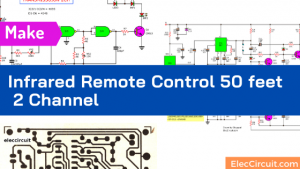
- Infrared Remote control 50 feet 2 Channel
- Small RF universal remote controls
How to build this project
If you want to make this project. First, you may test them on a breadboard. So easy to make.
Parts you will need
0.25W Resistors, tolerance: 5%
R1: 10K
R2: 470Ω
R3: 1M
VR1: 100K Potentiometer
Semiconductors and others:
Q1, Q2: BC558, 45V 0.1A, PNP TO-92 Transistor
Q3: EP103,
Phototransistor
9V battery
When you like it. You can assemble them into Universal Board as Figure 2 —the components layout—.
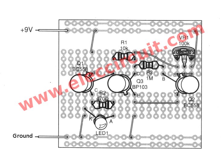
Figure 2 the components layout on universal PCB.
Keep reading:
- Coaxial cable tester circuit
- Simple Continuity Tester circuit using IC-4011
- The Op-amp IC tester circuit
Special Infrared receiver using LM1458 CD40103
As simple circuit above, If you want the circuit with special features, can set the program. To control the circuit works when you enter an input pulse signal of 1 to 256 times.
Look at the circuit diagram of the Infrared Receiver in a larger version as below.
How special infrared receiver circuit works
This contains 4 main parts of the work as follows: the signal receiver and filter circuit, the set waveform, the frequency divider, and the driver relay circuit.
The receiver signal and filter circuit. The component is received a signal is a photodiode D1, the signal across D1 will be sent to the filter circuit that will allow the 5KHz frequency only can through it.
Which consist of the feedback circuits R4, R5, and C2 that join with IC1. The determining circuit will cause a low frequency, this circuit has a gain equal to 1. But that frequency of 5 kHz will have a high gain of 1,000 times.
The 5Khz signal will be inserted into the double DC to DC converter include of D2, D3, R6, C4.

Figure 2 The special infrared receiver circuit
Setting IR receiver waveform
Since the waveform that may be inappropriate. We must set a new wave, which it has a range of up and down change quickly. Then, the setting circuits consist of a wave which is compared to IC1B. Input voltage with a defined voltage at Pin 2. will set a high output. But if the voltage lower than pin 2 then the voltage output is “0” This setting causes the noise signal that may be unusual to be eliminated. The LED-D4 is LED display of circuit. we know that the signal from the sender is entered the receiver to complete. Then, the IC2-CD4093 will set the waveform. Which IC2A and IC2B is the Schmitt trigger form. And the IC2C act as an inverter circuit. After that, the signal flow to the frequency divider-IC3-CD40103 The frequency divider circuit The frequency divider circuit works by using the divided frequency IC as a program types From the 2-256 number with setting the voltage at the control input pin. Which has 8 pin is the pin 4,5,6,7,10,11,12,13. The program is a binary base 2 by 1 = positive, 0 = ground. For LED-D5 show the working of the output pulse from the frequency divider circuit. Last, the output as above will flow to the transistor TR1 to the driver the relay to works as desired.Build Special IR receiver circuit
First of all, We can assemble all components of circuits onto the PCB. When you are sure all the wires and components are installed correctly. Next, experimental enter the DC power 9 volts to the receiver. It has scope hold at pin 3 of IC will see is the frequency bands 5Khz. But if there is no scope to capture the notice of the diodes will feel warm. After that, to connect the voltage to set the receiver signal to the photodiode LED D4, adjust VR1 until full brightness. Which normal is in the center. In general, we can use this receiver in a range of about 3.5 M. However, you want more than this far. You may use a combined optical blade. In addition, the photodiode should be in a sealed box, allowing only the aperture only. To avoid the signal of natural light. Setting counts number As above that, Setting counts possible input voltage at input pin counts to a decimal number by 2.

I love electronics. I have been learning about them through creating simple electronic circuits or small projects. And now I am also having my children do the same. Nevertheless, I hope you found the experiences we shared on this site useful and fulfilling.

good
Hi param.
Thanks for your feedback.
the first circuit wont work. the power supply is wrong. you would need a centre tapped transformer with the centre connected to earth to use this setup. the description is wrong and the english is terrible
Hello, john w,
I appreciate your advice. I accept mistakes to improve them.
I appreciate you taking the time to guide me. Hope you will visit my website again.
Thanks a lot.
Have a good day.
Perhaps you should reread your explanation and update it to reflect elements on diagrams. They are out of sync and if someone does not know electronics professionally then it will be incorrect explanation.
Hi,first of all thanks for your content
would you please tell me Have you ever tried this circuit?