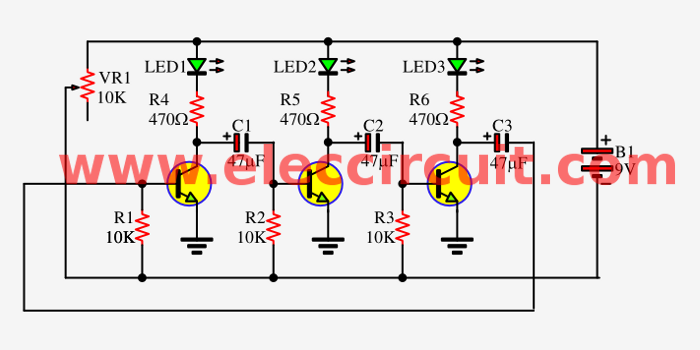
We used the two LED flasher with transistors only. Today we come to experiment the 3 LED flasher circuit as Figure 1 that also use astable mutivibrator with 3 transistors to drive all LEDs.
The Flash rate of LED1-LED3 in each frequencies output are easily changed simply by changing one, or three of the timing capacitors (C1, C2, C3). Which each capacitor does not need same capacitances.
The Resistors-10K are used to bias transistor conducting.
Then, we insert VR1-10K-potentiometer to control base current of transistors, which importance they are used to simply adjusts the flash rate.
And, each the 470 ohms resistors is used to control current flow through or limits current to each LED.
Read also: How does a transistor circuit work
We assemble all components into the breadboard as the video below.
You will see that, the LEDs alternately flash ON and OFF about once per second, always two LED will glow each time.
This circuit uses a 9V power supply. But if you want to use an LED flasher circuit use 1.5V or 1.2V this may be an option that you like (for 4 LEDs up).
Read also: DIY Flashing Bicycle LED Taillight Circuit
The components List
Q1-Q3: CS9013, 500mA 30V NPN transistors
C1-C3: 47uF 35V Electrolyte capacitors
VR1: 10K (B) Potentiometer single
R4-R6: 470 ohms, 0.25W resistors
R1-R3: 10K, 0.25W Resistors
LED1-LED3: LED as you want
PCB or breadboard.
Read more LED flasher circuits
- One LED flasher circuits
- Recycling free white SMD LED from e-waste
- 3 LED Chaser circuit using transistor without IC

I love electronics. I have been learning about them through creating simple electronic circuits or small projects. And now I am also having my children do the same. Nevertheless, I hope you found the experiences we shared on this site useful and fulfilling.
Awesome Circuit…THANKS!!!
this circuit look like having some problem or maybe most said it doesn’t work correctly because it’s clear to see after first LED lights the together second LED lights and fisrt one don’t off , I think even saw the 3ed LEDs lighed and 2 before wasen’t off yet , what kinds of Flasher or !!!? oscillators you calling this ? maybe a ring osc !?? I forgot names after 35 years pasting from my student time ,
Hi Mr OHM 1970,
Thanks so much my friend.
@admin,,This Is The #1 Electronics Site To Find USEFUL And ENTERTAINING CIRCUITS To Construct,,Thank You For All These Circuits!! I am a Hobbyist First and a Engineering Technologist Second!!!
Please, inform me, the BC CS9013 equivalent. Thank´s!
Dear friend, thank you for your awesome work!
About the “Three led flasher by 3 transistor astable multivibrator” it is almost the one I need! Almost because I need to light ONE led at once, insted of the TWO in your circuit.
Can you please help me to find out how could I have to do to achieve it?
Thank you very much!
Cheers from Italy
VR1 can short Battery – and + in one position when do full rotate…..!
Hi, Homebrew.
Thanks for your feedback.
Didn’t work!!!
Hi Kambaiz,
Thanks for your feedback.
But this works please watch video.
Hi momename, actually, i need this circuit but it didn’t work when i made the same i don’t know why? (I used transistor BC547)
And also guys, i need the driver circuit diagram for a single 3 watt ir (infrared) LED. My DC power will be 4.5v if possible. Anyone can help me pls? Thanks.
Hi! I’m just new to your website and find it very much interesting and educational. Regarding this circuit, If i’m going to use it using a 12Vdc supply, what changes should I make? Tnx
Thanks for the interesting circuit. I’m a total newby to hobby electronics.
I have a question if you don’t mind dose led1 light up when cap1 is charging. I’m just trying to work out how it works. Thanks again Simon
its awesome i need operation of this circuit
thanks a lot
can we blink four or more leds with this ckt??
Or can we use other type of tramsistors
Can i use s9014
EDWARDO,,YES If The S9014 is a NPN Transistor
Can you please send a picture of all the components mounted on the bread board, so that I can make connections properly. It’s difficult to see the exact points in the video.
Thanks for the circuit; this worked well for me. I am interested in having the timing on each LED be different. That is, can it be configured to have one LED on for 1 second, the next on for 2 seconds and the third on for 3 sec for example? Does this just require the single 10K variable resistor to be replaced with different resistors for each transistor?