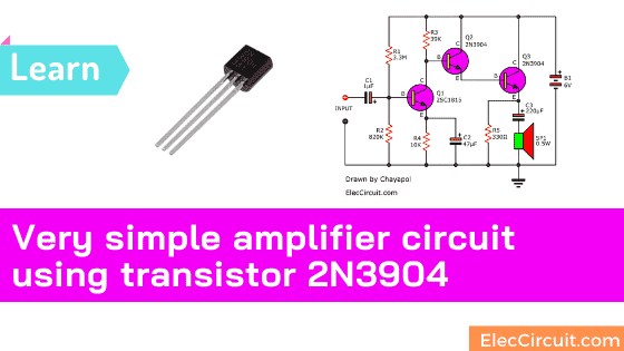
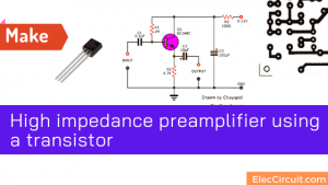
Today I get an email from Kunal Banerjee, send a preamplifier project to published for all to see. It is a very simple amplifier circuit using transistor 2N3904 only. Though very small, it still has many uses. Also, I am going to show you the tiny amplifier using 2N3904 below.
How it works
He says it low noise than normal IC circuits. and extremely low distortion. Frequency response: 20 Hz to 20 kHz.
It is a high gain but low power output and inverts signal output.
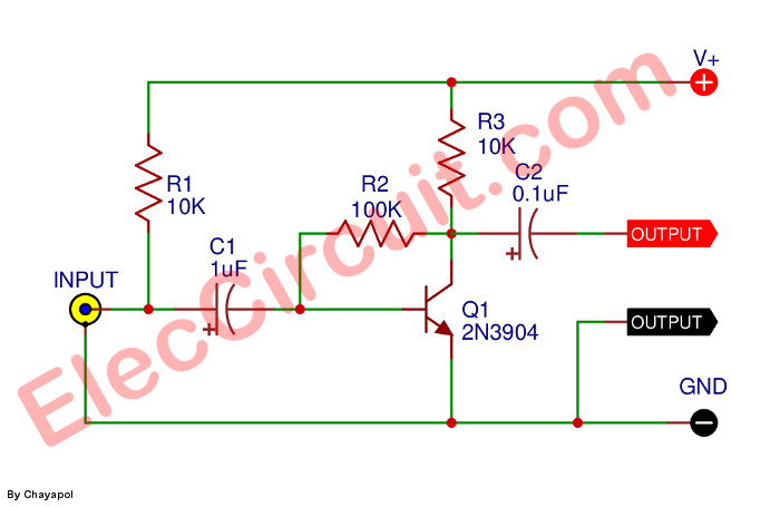
In-circuit diagram or schematic which is set circuit in the common emitter.
In electronics, a common emitter amplifier is used as a voltage amplifier.
In this circuit the base terminal of the transistor serves as the input, the collector is the output, and the emitter is common.
We can use this circuit to increase the lower signal to higher before send to a normal amplifier which low gain but high power.
Read also: How does a transistor circuit work
How to build it
Also He send me the PCB SILK as components layout see below.
PCB SILK
And the PCB layout.
PCB LAYOUT
Parts lists
Capacitor
C1: 1uF 25V Electrolytic
C2: 0.1uF 50V Ceramic or Mylar
Resistor
R1: 10K
R2: 100K
Q1: 2N3904, NPN transistor
Not only that see a higher power amplifier than this below.
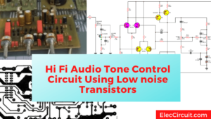
Basic transistors amplifier circuit using 2N3904
This is a basic transistor amplifier circuit. It is suitable to learn how the transistor works.
We can divide the operating range of the transistor into 3 ranges.
- CUT-OFF is that the transistor will stop working, in this period there will be no base current (IB) and collector current (IC).
- Saturation range is the period that the current flows through the transistor fully until it reaches saturation. And the current will not flow anymore.
- The active range is the period in which a transistor operates to conduct the current. We can find the current gain (hFE) from hFE = Ic / Ib.
Therefore, using the audio transistor will arrange the circuit to work in the active phase. Which we will use the current gain of the transistor.
Read also: How transistor works
How it works
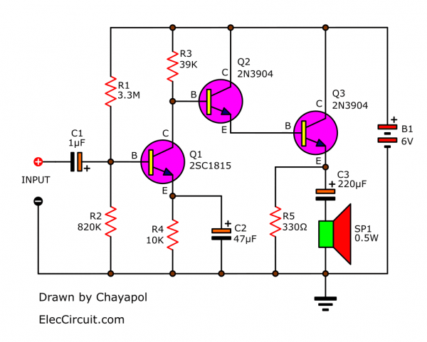
When there is an input signal, it will pass through C1. To filter out only the sound signal, then feed to Q1 at lead B. It is the first expansion(preamplifier). Which designers organize the amplifier circuit in the common-emitter form.
And, there are R1 and R2 to connect in the voltage divider circuit for the Q1. But the output signal at the collector (C) not strong enough.
It needs to increase this signal by Q2 and Q3 again. Which Q2 and Q3 ต่อกันเป็น the Darlington circuit. It is the connection of 2 transistors with similar characteristics. Therefore the gain is more expansion.
Some people call it hFE2. For example, if each transistor has hFE = 100, the total gain will be equal to (100×100) = 10,000 times. From there, the amplified signal is driven to the SP1 loudspeaker pass C3.
Parts you will need
0.25W Resistors, tolerance: 5%
- R1: 3.3M
- R2: 820K
- R3: 39K
- R4: 10K
- R5: 330 ohms
Capacitors
- C1: 1uF 16V
- C2: 47uF 16V
- C3: 220uF 16V
Semiconductors and others
- Q1: 2SC1815, 45V 0.1A, NPN Transistor
- Q2,Q3: 2N3904, 40V 0.2A NPN transistor
- SP1: 8ohms Speaker 0.5W
- B1: 6V battery
Hand-picked related articles you may want to read:
- 4 transistor audio amplifier circuit
- 7 Simple audio amplifier circuit diagram using transistor
- Dynamic Microphone Preamplifier circuit
Related Posts


I love electronics. I have been learning about them through creating simple electronic circuits or small projects. And now I am also having my children do the same. Nevertheless, I hope you found the experiences we shared on this site useful and fulfilling.
hi,
how many DC volts are required to operate this circuit.
I got a schematic similar at 9 volts
hi,
how many power supply volts are required to operate this circuit?
The power supply can be 3 to 12~15V DC 1A max, also it works good with less the 0.5=500mA
can use it for nrf 24L01 rf module
can i fix both transmitter or receiver or transmitter
Why do you need R1 it is not necessary
Hi Levent,
Thanks for your question.
This circuit is interesting. You pick it well.
R1 is a bias resistor for the condenser microphone. Yes, if you use a dynamic microphone. It does not necessary.
Anyone have info on using a 2N3904 as a rf amplifier for TV antenna
Did you ever have any luck with this???
i was juuuust about to try the exact thing for my grandfather who recently decided to tell the cable company where to cram it. thing is, I’ve got a mountain of 2N3904s but I’ve also got a little stash of about a dozen other fairly common BJTs as well. 2SC1815, 2N2222, the 901x family, 2N5551, etc. Plus a few types of JFETs and a couple types of MOSFETs. So I was just wondering if you did attempt this idea, which transistor you landed on for it and how that all panned out.
I’ve never really messed with anything for such high frequencies, and I’m only self-taught in this stuff, but it would be killer for my grandfather if it worked and for me also. If you get this message, and care to share any info, I’d be immensely appreciative. Thanks in advance!
I wouldn’t call it an amplifier circuit. I put in 80 decibels and got 79dB out
Hello Jeff,
You are right. It is too small.
And the second circuit?
Thanks
you talking about the final three-BJT “amplifier?” saving me some time and aggravation with the heads-up if so. i appreciate it.
i just assumed since the darlington section, were both configured as common collectors (i.e. buffers basically, but high current gain; **about** unity voltage gain), that the current would be boosted skyward, hence providing the power gain to drive the output.
but i didnt go to school for any of this stuff, brother. them’s just my own guesses after scoping it over for a second. i could be horrendously incorrect, and very many times am. so your mileage may vary with that info. or your… meter-age?? is that what people in other countries say about their vehicles?? …weird, man…. but whatever floats your pontoon, jack.