3 LED Chaser circuit using transistor without IC
Let’s make 3 LED chaser circuits using transistors without ICs. We will learn how transistors work as switches with capacitor discharge. Read more
More LED chaser and LED running Lighting
Let’s make 3 LED chaser circuits using transistors without ICs. We will learn how transistors work as switches with capacitor discharge. Read more
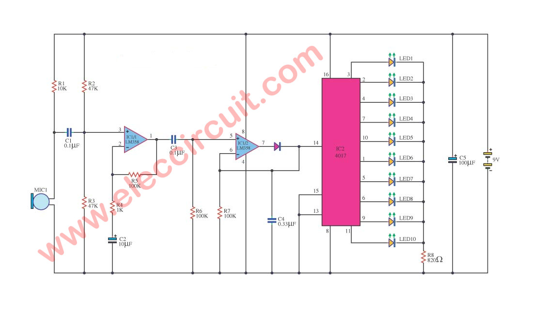
This is a circuit that features a running pace with a changing voice, the tiny microphone. For a frivolous fun. Read more

Here are LED light sequencer circuit that using IC-4017 and IC-555. Read more
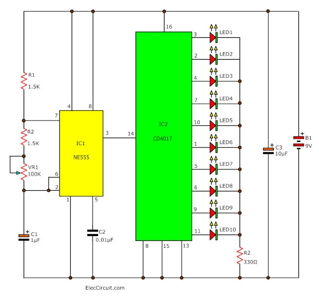
If you want to build a 10 LED Chaser circuit we suggest this circuit first. It uses popular IC is a simple and affordable IC-4017_decade counter and IC 555 […] Read more
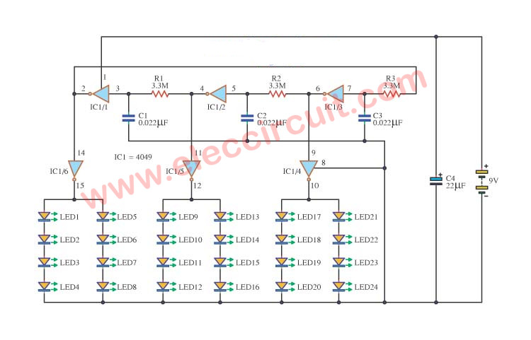
I am going to show you, LED Decorative light circuit. Do you like a LED blink or running light? I like a circuit like this. Although you will do not build it now. But it also a good teacher, right? If you have ever been to use a LED flasher. Some may wonder how the … Read more