This is a general-purpose bass booster circuit. Why should you use this?
You are listening to your favorite song. But it lacks many flavors. Friends said No Bass! Buy a new one amplifier right now.
Stop…
It is true. Your amplifier may less bass. But before buying a new amplifier. Try this, it probably better.
Solving this problem
Most friends have a preamplifier with tone control. Did you try adjusting the bass button?
Sure, rotate it almost broken. Not get more! petty sad.
Do not despond.
What does basic work?
It is a low pass filter circuit that looks like a bass function on the tone control. But it works well than that.
Sound good, is it? Let’s get started.
How Active Bass Booster circuit works
Look at a circuit below. This circuit has been popular more than 40 years ago.
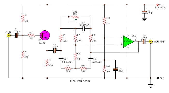
Figure 1 The schematic diagram of this project.
Thanks, the designer makes us enjoy it. It looks like a normal tone control circuit, right?
Yes…
Related: The super pre tone control projects
High frequency is in Flat mode. But Low frequency or BASS. We can turn up or down with adjusting VR1. It is so easy.
So what?
Here is a step-by-step process:
When feeding an audio signal to the input.
A C1 is a coupling capacitor. It passes on AC to a base of Q1 through R3. And both R1 and R2 are a voltage divider to bias current of Q1.
We will see that Q1, C1, R1, R2, R3, R4, and C2 connected together as a normal preamplifier circuit.
They will boost up a signal up to one level first.
Then, higher single go out of emitter of Q1 through C2 coupling signal to low pass filter section as above.
Then, a first signal flows through C3, C5, R8, R9, and R10. They will eradicate a high frequency away. And another signal get into R5, R6, R7, and C4.
They are a low pass frequency filter circuit.
We can change the low-frequency level or the bass sound much or less by adjusting VR1.
Then, both signals are mixed together at pin 2 of IC1, 741 op-amps. It is one of the popular IC. And IC1 amplifies them more level up out of pin 6 to the output.
And, some signals from pin 6 feedback to the frequency filter again. To control the gains on frequency ratio that high stability of the circuit. Before sending it to the external preamplifier next.
This circuit requires 12V to 18V DC power supply. You should regulate form only. To reduce any noise. For example:
Bass booster Connection
There are 2 types of connections, the magnification of the amplifier as follows. (Look at Figure 2)
(1.) The application with power amplifiers that power output less than 60 watts.
To apply the audio signal to the tone control circuit to this circuit and then to input amplifier circuits
(2). This way is best, connecting it to font the original tone control circuit for more than 60 watts power amplifiers.
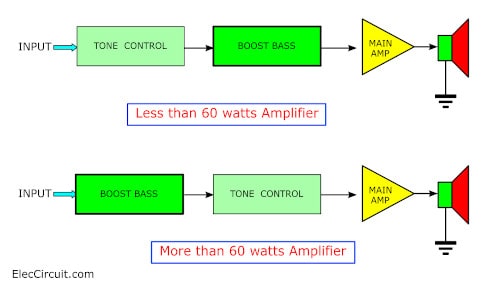
Figure 2 Connection
However, consider the watt amplifier, If you want best results, should be connected to the front sets the tone control is better.
Here are a few related Projets you might want to read:
- 3 Preamplifier with tone controls
- Instant Stereo Tone control TDA1524A
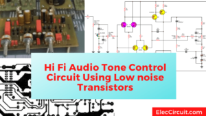
- Low noise Tone control using common transistors
How to build
Crease the PCBs as for MONO and for Stereo. As you see appropriate. Then Assembling parts into the PCBs in the correct order.

Here are the PCB layout and components for MONO
And See in stereo form.
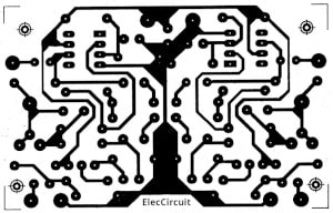
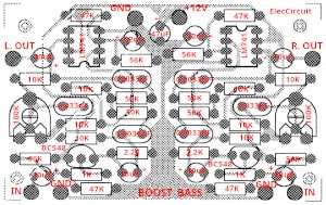
Figure 4 The PCB layout and components for Stereo
Then try to apply the power supply to the circuit. Then adjust VR1 to the best bass as you want.
Caution
This circuit is not suitable for low-watts amplifiers. And the speaker who can not get the bass sound.
The parts you will need
IC1: LM741, General-Purpose Operational Amplifier
Q1: BC549, 45V 100mA NPN Transistor
0.25W Resistors, tolerance: 5%
R1, R12: 56K
R3: 1K
R2, R11: 47K
R5, R6, R7, R8: 10K
R9, R10: 50K
VR1: Preset 100K
Electrolytic Capacitors
C1, C2, C8: 10uF 16V
C6: 47uF 16V
C7: 22uF 16V
Ceramic capacitors
C3, C5: 0.0033 uF 50V
C4: 0.033 uF 50V
Not only that!
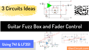
You like the transistor circuit, right? Look at this:
Bass booster using transistor I like it, too. Because of low noise and I have a lot of old components. No outdate.
Related Posts

I love electronics. I have been learning about them through creating simple electronic circuits or small projects. And now I am also having my children do the same. Nevertheless, I hope you found the experiences we shared on this site useful and fulfilling.
C4,C3,C5 pls are they pf uf or nf pls help me..
Pls C4,C3,C5 are they pf uf or nf pls help me.becuz of non polarity
Is this circuit work?
@Mensah,,,,,uf,,uf,,uf
Hi There,
I have built your bass booster and it works very well. Are you able to tell me what frequency range it uses.
Many Thanks
Grant
Hi Grant,
Thanks your interested this projects it easy.
it boost up at 60Hz frequency but you can adjust more frequency as you want please read it text again.
what is the supply for this circuit sir 12v 0 12v ?
please help me for doing this project
i can’t understand the process of constrcting bassbooster
please help me for doing this project
i can’t understand the process of constrcting bassbooster
thanks
Sir i have built ur circult but when i connect it to amplifier and speaker,i got noise alongside bass..
Please tell me how to fix it…..
is this a 30 watt speaker ?
please !! I want reply immediately : (Good) && Is op amp pin 2 and 3 voltage are same? and why??
I want to make a tone controller