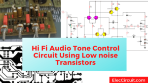
Are you wanting to hear good music? There are many factors to do. But this is an important thing that you should not overlook.
I recommend a bass mid treble Tone control circuit using an op-amp.
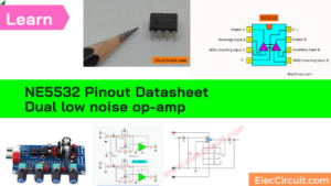
You should choose to use the NE5532 as main, it is so an interesting IC. Because of the ultra-low noise properties.
So often uses them in a Hi-Fi audio system. Here are small circuits with a PCB layout.
I hope they will be useful to you. Good luck, thanks.
Look at 5 circuits, from small to LARGE below:
.
Pre Tone Control Stereo using NE5532
First circuit diagram. If you want a good simple Pre Tone Control circuit in Stereo. I recommend this circuit in your choice.
Because it uses only one NE5532. It is a high-quality IC, inexpensive extremely.
Look at the circuit.
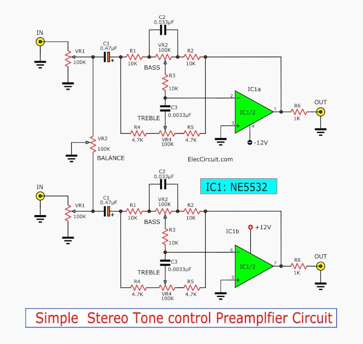
Simple Stereo Tone Control PreAmplifier circuit NE5532
Although, it is a small stereo(2 channel) circuit. But it has a full option to adjust the sound.
In this circuit, you can adjust the bass, treble sound well, and high-low sound in easy.
Also, set a balance of the sound everything is completed.
You may use your skill to try to build the circuit in easy with the PCB layout Below.
Look below.
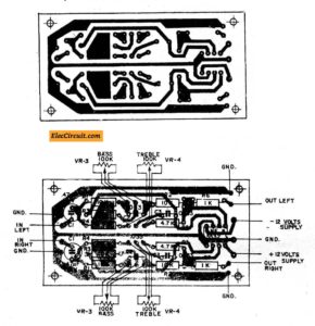
PCB layout & Component layout of Simple Pre Tone Control
What is more?
Sometime you may want more adjusting.
Read NE5532 datasheet and pinout
Bass-Mid range-Treble Pre Tone Control
If you do not like the first circuit. Because it cannot adjust all full range of sound.
This is the second circuit. It still fully adjusting to Pre Tone Control in Stereo.
You adjustable Bass, midrange and treble.
So, you can adjust full-range sound easily.
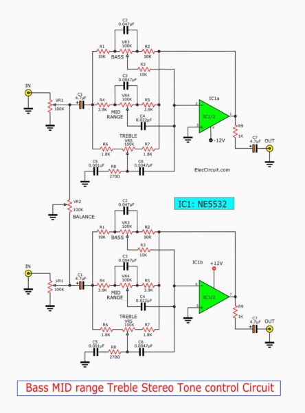
Bass, MID range, Treble Stereo Tone Control circuit
Easy to build, PCB small.
Look:
PCB layout of Pre Tone Control Stereo (bass-mid range-treble)
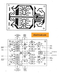
High Gain Stereo Tone Control (bass-treble) using NE5532
If you do not like the first circuit. Because it may low power output so cannot really use with a very small input signal.
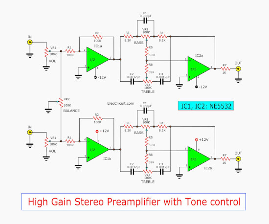
My friends want a tone Control Stereo circuit. It can control the sound bass-treble-volume well. And it is a high gain more than two circuits above.
Then, I found this circuit, Tone Control Stereo (bass-treble) using two NE5532.
Also, it uses an integrated circuit op-amp that is low many noises or low noise. So, it makes a good sound and easy to build too.
This circuit uses two integrated circuits. So it can amplify a smaller signal input to a power amplifier.
Not only that you can see better circuit with high gain circuit.
Look at circuit below:
Low noise pre tone control circuit using 4558 – NE5532
In fact, 3 circuits above for beginner and cheap. But Do you want a better version?
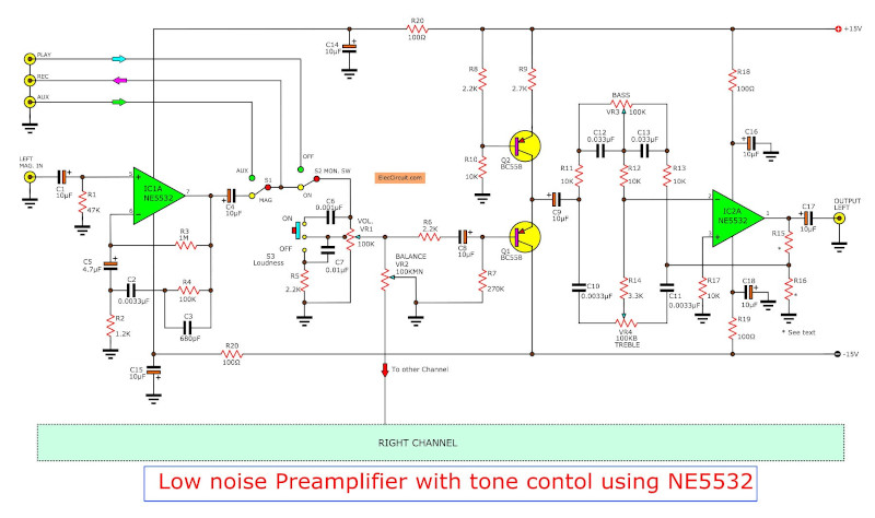
Circuit diagram of Low noise pre tone control circuit using NE55532
It uses a NE5532 as the key of the circuit. It was very interesting ICs. Because have special features of low signal noise. You will commonly use it in a high-class amplifier.
My friend said me, if you want a low and high frequency of sound, use RC4558 instead.
To avoid hum noise on the background. Use: 15V Dual power supply
How to build
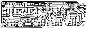
You can assemble all parts on the PCB & Components layout as below.
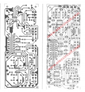
The actual size of the single-sided copper PCB layout and the component layout.
Be careful list:
- The polarity of electrolyte capacitors must be correctly put on PCB.
- On PCB layout is used for transistors – BC557 or BC560C noise transistors types.
- If the number MPSA42 switches the position of the emitter and collector to the opposite direction.
- Be Careful of a beginner at every point soldering Requires heating the solder sufficiently to ensure that all solder points are very well equipped.
- Do not heat the solder too hot. Because May cause equipment damage And copper may be peeling off.
- How to help the solder is easy to clean pins all the time.
- When assembled and checked well. To apply the power supply to this circuit connects correctly.
- Connect the output of the circuit to the main amplifier and bring the good signal to the input of the circuit.
- Check the operation of the circuit by adjusting the Knob. Obtain the desired result.
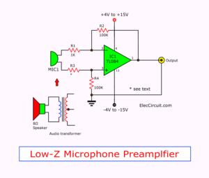
Modify the pre mic circuit
- Those who want to use the pre microphone, you can modify circuit to new as Figure 3 The feedback circuit for microphone
Shopping List
- IC1: NE5532 low noise OP-AMP or LM1458 or JRC4558
- Q1, Q2: BC557 or MPSA42, PNP 0.1A 40V Transistors
- 0.25W 1% Resistors
- R1: 47K
- R2: 1.2K
- R3: 1M
- R4: 100K
- R5, R6, R8, R14: 2.2K
- R7: 270K
- R9: 1.2K
- R11,R12,R13,R17: 10K
- R14: 3.3K
- R15: 4.7K
- R16: 470 ohms
- R18, R19, R20, R21: 100 ohms 0.5W 1% Resistors
See these circuit may like them
- 3 Low Noise Microphone Preamplifier
- Universal Preamplifier using NE5532, LM382, 741
- Treble Booster Circuit using 741
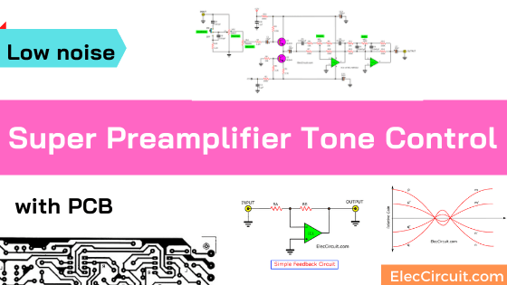
Super Pre Tone Control Project using LF353
Why we use the active tone control Baxandall type circuit? You will get an answer here. And you may love and build it.
First, learn a little about tone controls:
Types of tone controls
We can divide the normal type of tone control are 2 types as follows.
- Passive Tone Control
- Active Tone Control
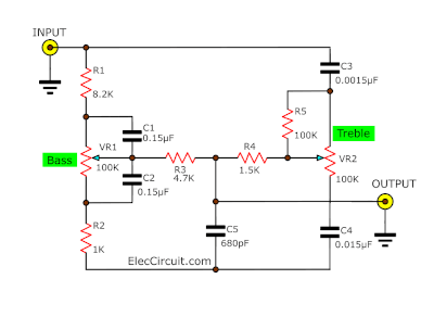
Passive tone control
A style of the passive tone control circuit is shown in figure 1. We do not widely use this circuit. Because sound quality is reduced and low performance.
Active Tone Control
We like to use it. the active tone control type that most familiar. is the Baxandall type circuit As shown below.
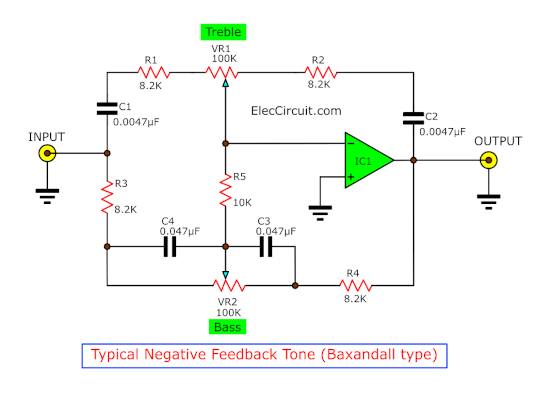
The advantage of this active tone control type is not caused loss signal.
How does the circuit work
We may understand the function of this circuit easier. By considering the comparison of the circuit in Figure.
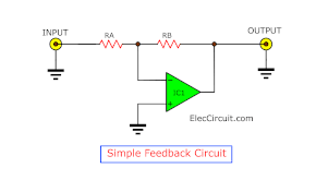
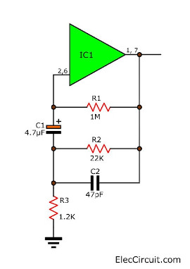
The simple feedback circuit
See that the gain of the circuit is equal to the Rb / Ra. So
- Rb = 10, Ra we have gain = 10.
- Ra=Rb, The gain will be 1
If we return to consider in figure 2, will see that C1, R1 & C2 + R2 are connected together that the value its Impedance will decrease as the frequency increases.
If we adjust VR1, the Ra1 value is greater than C1 + R1. Then, the gain of line M in figure 4.
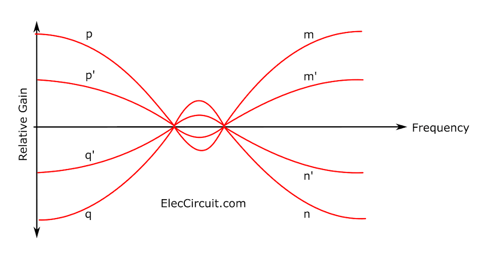
On the contrary, if we adjust the volume in the other direction. Will have gain of the circuit as line N. In figure 4 VR1 serves as the Treble control.
Then consider the P3 + C3 and C4 + R4 will see that resistance is even higher. When lower frequency so has the gain of the circuit as figure 4 then P, Q to R5-resistor that serves as a separate circuit, the 2 parts, not to interfere with each other.
Which in practice. Can not be strictly separated circuits. That is when we adjust the bass – treble would be with prejudice.
how to modify so Maybe split both control circuit independent decisively as shown in figure 5
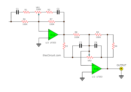
Sequential two-stage tone control which avoids inter-action between controls.
From these principles, we can design the tone control circuit solutions.As circuit shown in Figure 6.
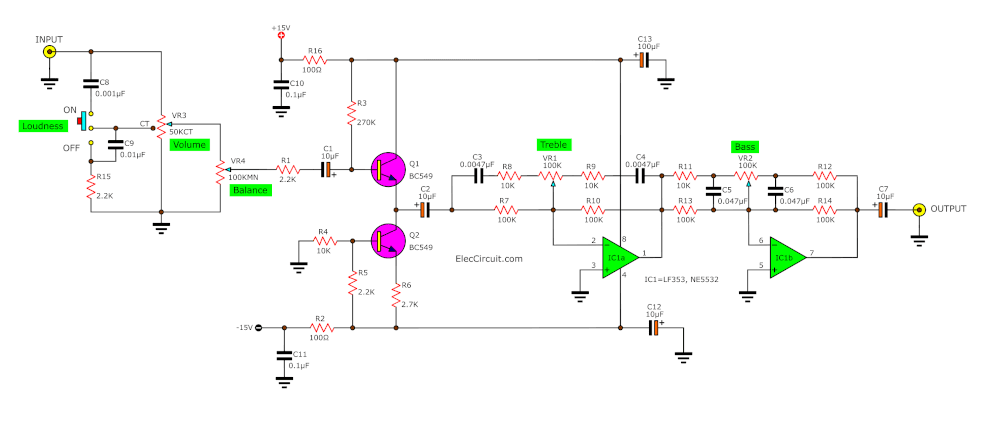
See Full Super tone control circuit diagram
We use the circuit of Q1, Q2 transistor acts as a Matching circuit. Between input and this super tone control. We connect Q1, emitter follower type. And have Q2 is a constant current source circuit.
The IC1-LF353 will act as the adjust the treble sound. And IC2-NE5532N serves as a fine bass voice. Because the normal tone control and pre-amplifier will work best well.
When they drive a circuit with low impedance, and the load applied to high resistance.
How to build
Make a PCB as PCB layout and Assemble them as positioning devices. I believe you can do it.
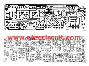
Figure 7 PCB of Super tone control
PCB layout of this project
The Shopping List
- IC1: LF353, Wide Bandwidth Dual JFET Input Operational Amplifier or NE5532N
- Q1, Q2: BC549, 45V 100mA NPN Transistor
0.25W +/- 1% Resistors
- R1, R5, R15: 2.2K
- R2, R16: 100 ohms
- R3: 270K
- R4, R8, R9, R11, R12: 10K
- R6: 2.2K
- R7, R10, R13, R14: 100K
- R15: 3.3K
- VR1, VR2: 100KB Linear Potentiometer
- VR3: 50KA CT non-Linear Potentiometer
Electrolytic Capacitors
- C1, C2, C7: 10uF 16V
- C12, C13: 100uF 25V
Polyester Capacitor
- C3, C4: 0.0047uF 50V
- C5, C6: 0.047uF 50V
- C8: 0.001uF 50V
- C9: 0.01uF 50V
- C10, C11: 0.1uF 50V
Download This
All full-size images of this post are in this Ebook: Elec Circuit vol. 2 below. Please support me. 🙂
Conclusion
You should use a good quality of DC dual regulator power supply,+12V and -12V.
12V Dual Power Supply, 80mA min. It has Positive, Negative, Ground. You may use the 7812-7912 DC regulator.
Besides, IC1 and IC2 use, the number can replace many the number such as NE5532 or LF353 or RC4558, etc.
…
If these circuits don’t clear.
Try other circuits using low noise transistors by the list below
- 7 tone control circuit diagram with PCB layout — There are many circuits for you to choose 2 to 5 transistors. They are easy but give a nice sound.
- High-quality tone control circuit diagram — Use all 8 low noise transistors, as a high gain pre-amplifier circuit. So, it is a great circuit in your Hi-Fi sound system.

Related Posts

I love electronics. I have been learning about them through creating simple electronic circuits or small projects. And now I am also having my children do the same. Nevertheless, I hope you found the experiences we shared on this site useful and fulfilling.
Thanks & very usefull..
now I am using this preamp for my power amplifire. working fine best sound quality
I (I used RC4558 ic)
Sorry for my bad english. 🙁
Hi, sanjeewa
Thanks for your feedback.
Hi,
I am from Poland and I want to build pre tone control (3 bands) on NE5532. My question is: How will be work this preamp with IC TDA7560?
I think it will be best working to tda
3 preamplifier circuit some errors in the IC leg numbering please correct it
Hi.
I want to build this circuit, I want to use it together with a bass-guitar amp. My question is, the circuit looks like two circuits that results in two inputs and two outputs. If my output will be on only one speaker, do I need the two circuits coupled by the “balance potentiometer”, or can I just build one with one input and one output?
Hi All,
I want to make a stereo pre amplifier with bass ans treble control.
Have anyone made this circuits? please tell me which one is the best.
Thanks,
Nuwan,
Hi.. I found this circuit is very useful..one thing I need to know can I use the first section only..i.e. the first opamp circuit before the baxandall tone control circuit as an audio preamplifier??
thanks in advance
Hi,Partha
Thanks for your feedback.
This also useful for you. https://www.eleccircuit.com/tag/audio-preamplifiers/
nice preamp design thank you so much for free.
Hi thanks for the circuits. I have a question for the schematic No.1
I have a hard time understanding the capacitor values.
0.47µF (electrolytic or ceramic)
0.033µF = 33nF
0.0033µF = 3.3nF
Hi sir
I am trying my best to understand your English.
Of course that is not so important.
Sir
I am planning to build a High quality, High Power( >= 300 watt(rms)) Amplifier.
I need a very high quality Pre-amp with Bass, Treble, Blance and Loudness control.
I also need a 10 band Graphic Equalizer.
Could you please suggest which Configuration is best.
1. Do you have ready made Pcb’s for all these. 2. If you have How much is the cost.
You can write it to my personal email ([email protected]). I want it to use it at home. I am fedup with all these so called Home theaters.
Regards
Sen
Hi, nice design, but can you please publish here what kind of capacitors each capacitor are in the circuit? if it is ceramic or polyester or electrolytic? and the capacitors are all express in microfarad right? tnx in advance! i want to build the 2nd design, which has a midrange.
i,m hoping for your help guix.
hi, nice circuits, but can you please post here what kind of capacitor each capacitor in the circuit #2 if it is polyester or ceramic or electrolytic?, because i want to build it, tnx in advance,
Hi , I want to know this Tone Control can be used with 2 X 4440 circuit.
where is volume and and balance in pcb layout of Pre Tone Control Stereo (bass-mid range-treble) by IC NE5532 ?..
You can make it by using a 100k potentiometer
You have to do common to pin third for ground and the middle 2 pins is for audio out and the last both pins of first number will be audio input
You can give input on pin first left and right from your Bluetooth module or mobile jeck
Then the 2 pins of middle . You can put the audio out to your 4440 board input.
Ground will be on last third both pins
The volume will be work definitely 👍
where is volume and and balance in pcb layout of Pre Tone Control Stereo (bass-mid range-treble) by IC NE5532 ?..
What is the size of pcb layout sir? Thank you so much. This ckt. Its so good
pcb size in design 2 Pre Tone Control Stereo (bass-mid range-treble) by IC NE5532
Nice preamp design thank you so much for free. Great people’s are helps the others
Thanks for your feedback
The last circuit , How many gains?
Hi sasd,
The gain of op-amp is approximately 1 times. Please see the circuit https://www.eleccircuit.com/low-noise-pre-tone-control-circuit-using-ne55532/
Hiii my Name is Carlos. I do it with an oa jrc4558 and it work so well. Thank u so much.
Can I used this same circuit JRC4558 ic
Hello,
Thanks for your visit. I am happy you are interested this circuit.
Yes, you can use JRC4558. It sounds great,too.
What is THD?
Hello Pedro,
Thanks for your visit. Your question is interesting.
THD is a TOTAL HARMONIC DISTORTION. This value is less good.
For example, 1% is better than 10%.
Thanks
Apichet
Sir can I use this circuit on YouTube just education purpose….