Lead-Acid Battery is the most popular. Though they are a very large size. But they have an advantage are: cheap, easy to buy. If you need a long life. You should use an Automatic battery charger circuit below.

Charging best importance
Usually, these battery types can use for 3-4 years with correctly charging. I feel sick every time the battery breaks down before the time should. I do not want you to be like me. Do not do these!
- Overheat charging
The important, battery does not like hot! At all time, do not use or store them in too heat area.OR If while use may short circuit or high current use them will too hot. While charging does not quick charge with high current and high voltage. - DC voltage only!
We must charge them with DC voltage only. - Overvoltage charging
Normally, the battery manufacturer usually prints the appropriate voltage.
We should use a constant voltage charge.
—12V battery maximum voltage of 14.8V, Standby use is 13.8V
—6V battery maximum voltage of 7.5V, Standby use is 6.8V - High current fast charge
But hot—So you should use initial current less 30%. For example, 12V/7AH battery you should the initial current less 2A. If we use 1A, the battery will be full for about 7 hours. - No long time
Also, If you charge it for too long times. The battery is also too hot. Thus, When the battery is full, stop charging it.
These two circuits help make your life easier.
Simple Automatic battery charger circuit
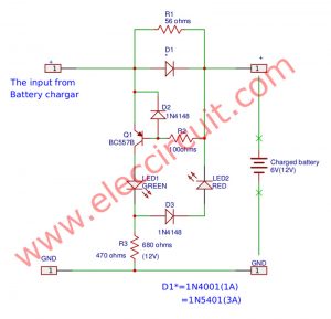
This is the first automatic battery charger circuit. We use the concept of the circuit: not using ICs and complicated devices. Use existing products to use more benefits.
We can use this circuit for all battery. Just have to understand Battery charging requirements only.
- It is designed for 12V batteries. But if you understand the working principle already. I believe you can definitely adapt for a 6V battery or others.
- You should use an input voltage of 15-volts or 1.5 times of a battery voltage.
- Most importance—Should use charger current 10 % of battery current. For example 2.5Ah battery. Use the charging current 0.25A. It will take 10-12 hour for full.
How it works
First of all, I think “When…Charge? And When stop?”
Normally we should charge the battery if the voltage is lower than 12.4V. Then the battery voltage rises and the voltage maximum 14.4V. It is full. We need to cut off the charging current.
Secondly, we need to use a comparator circuit.
I often use IC-op-amp such as LM339, LM311, LM324, LM301. But sometimes we cannot buy them.
And This our working is simple style only.
In the begin, we learn a basic principle of electronic parts.
Meet Zener Diode
I like use Diode, Zener diode, which they are both valves for electrical currents. The Current will flow one way. But the Zener diode is connected backward. It then blocks current until the voltage exceeds a certain level.
I try to test them with the Zener diode 12-volts the current will flow through it when a voltage higher than 12V.
So, I use Zener diode for detects voltage over than 13V to control stop charger system.
Relay and SCR cut-off battery
Then, I use a relay to control the current to a battery. Because of cheap and used easily.
Next, I use a SCR for uses as quick control switch.
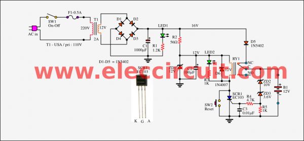
Simple automatic cut off battery charger
Comes to look in the circuit. I use it for 12V 7AH battery and lower. So the charging current is 2A.
So I use a 2A, 12V transformer in the unregulated power supply. In load or while in charge is 13V to 15VDC.
Suppose, the voltage battery is 12.4V. The relay does not work. The charging current flows continuously through the battery.
Until the voltage of the battery rises up to 13.8V. Starts to has the current flowing through Zener diode to Bias SCR1.
The SCR1 is working. Then replay also runs, pull in the NO and C connecting.
So no current flow to the battery.
How to setting and use
You can watch the video below I test it. This projects will always cut off the battery. When the voltage drops across it are 13.6V down.
Then LED2 (yellow) glow brightly. While the relay will pull out from the contact NC-C. Which no current to battery and voltage lower down.
Then you can charge again with pressing SW2 to reset, recharge them again.
High current charging
If you want to charge the high current battery. For example, 45Ah battery. You should use the current less than 5A. And less than 15A current.
Also, you need to use a high current power supply. The components inside are high current. For example 10A-15A transformer, 25A bride Diodes, 20A Relay and more.
I think this circuit is not suitable for high current battery. Because it may error charging. You need to use a constant voltage charge in PWM mode.
Automatic OFF 12V Battery Charger by power SCR
The circuit above may error and hard to set. I suggest an Auto dry battery charger using SCR for 12V battery. Also, it uses the 6V battery. It looks like the above circuit. The Zener diode and SCR are main parts. But the SCR works instead of the relay. The SCR is working in DC pulse on filters with a capacitor.
How this circuit works
As circuit below. To begin with, an AC220V will flow to a transformer to transform to 15 volts. Then, flow to bridge diode to rectifier AC to DC pulse 15V. The LED1 is a power indicator of the circuit.
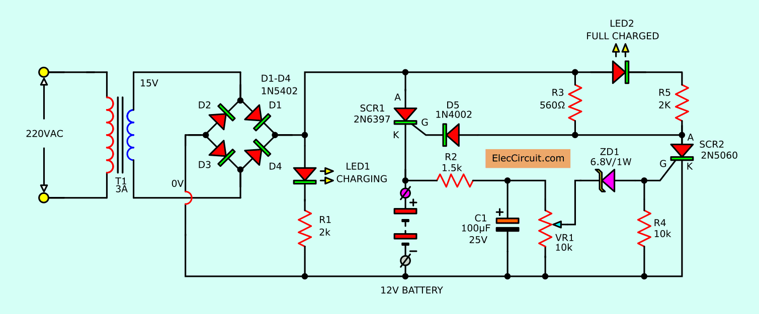
Beginning SCR1 is working. Because the 15V flow to R3, to limit the current to decrease and flow through to diode D5.
It protects the reverse voltage before bias to lead G of SCR1.
When SCR1 conducts, make the 15V flow through lead K to a positive battery terminal.
Ideally, SCR1 will conduct current and stop current alternately very fast with a frequency of 100 Hz.
Since the 15V voltage from the bridge diode is a full-wave rectifier. So the output frequency of 50Hz+50 Hz. The current of this feature is a continuous positive half of the sine wave.
Which it is different from the voltage with a capacitor filter, which is smooth as a straight line.
So SCR1 does not conduct the current all time. When there is the positive voltage to bias at lead G.
Since the waveform of voltage is DC pulse, not smooth.
The SCR will stop conducting current. If disconnecting is not a positive voltage.
Then, the positive voltage waveform comes to SCR1 again. It will start conducting currents again, this was reversed with a frequency of 100 Hz.
Recommended: Gel cell battery charger circuit
Battery level monitoring
To begin with, the positive battery voltage flows through R2 to reduce current. And, C1 will filter a current to smooth.
Second, the current flows through VR1 to divide voltage down. Then, the Zener diode-ZD1 pass an overvoltage to bias lead G of SCR2.
We adjust a level of VR1 to set a full battery. Until voltage at negative of ZD1 is more than 6.8V or about 7.3V.
After that, ZD1 is saturation voltage collapse flow through to feed lead G of SCR2. It causes SCR2 to conducts current. By R4 is a helper to SCR2 extraordinary stable work.
When SCR2 work, causes a negative voltage flows to lead K to A. It results to LED2 glow.
And the same time SCR1 will stop conducting current.
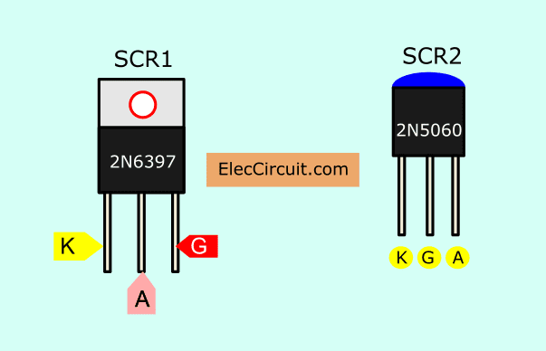
Pinout of TO-220 and TO-92 of SCRs
Since lead G of SCR1 get negative voltage from SCR2 there. In the case of battery is lower voltage, causes the voltage at negative of ZD1 is lower than 6.8V.
It makes lead G of SCR2 does not get positive voltage. But it can get only negative voltage through R4, result SCR2 does not conduct current.
The parts list
0.5W Resistors5%
R1, R5: 2K
R2: 1.5K
R3: 560Ω
R4: 10K
VR1: 10K Potentiometer
C1: 100uF 25V Electrolytic capacitor
SCR1: 2N6397__SCR
SCR2: EC103 or 2N5060SCR
ZD1: 6.8V 1W
D1-D4: 1N5404_Diode
D5: 1N4002_Diode
LED1, LED2: 5M LED as you want
PCB, and others, etc.
How to make and setting
- After you get all the components ready. Then, we soldered it successfully on PCB as Figure next checked again. For example, The device has a positive – negative. Are they correct polarity?
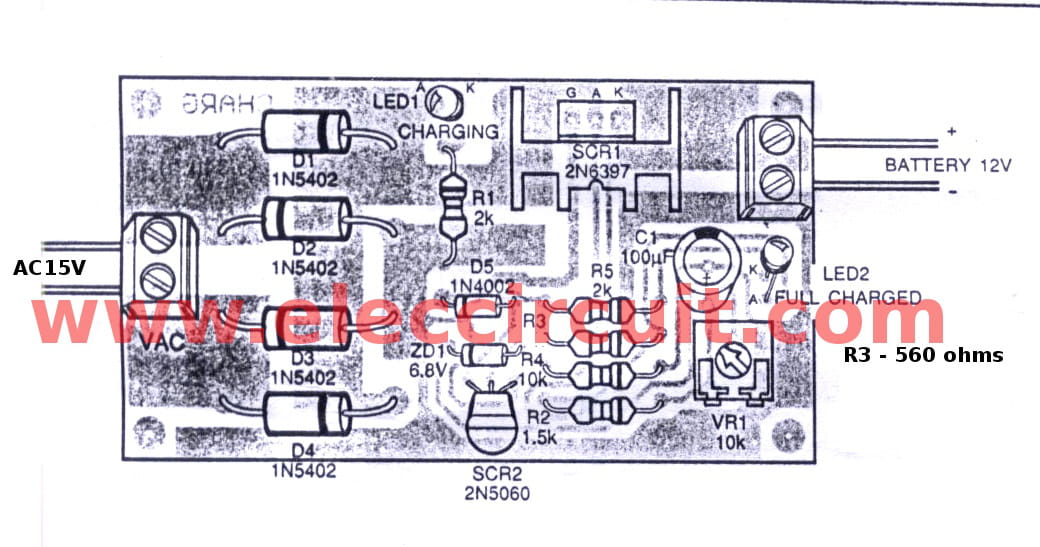
The component layout of Dry battery charger
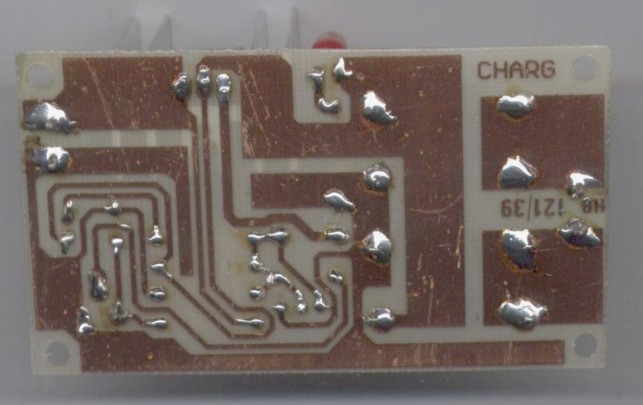
Soldering point of dry battery charger
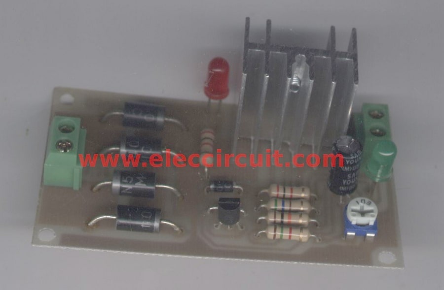
Complete assembly all parts on PCB
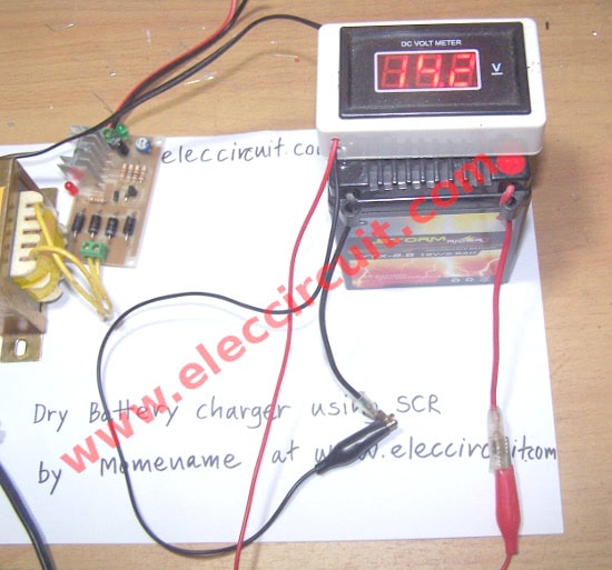
Fully 12v battery 2.5A
- To Safety, the first step, find a full battery voltage be connected to the circuit to correct polarity.
- Apply AC220V. Next, adjust VR1 clockwise until LED2 go out.
- To rotate VR1 clockwise slowly until LED2 light up, then stop immediately. Do not too much rotating.
- The principle of LED2 will light up when battery voltage until full. So, at the first time, the battery needs to be really full voltage.
Note:
I am sorry, I cannot show you the PCB layout. But you can use the perforated board.
Please watch the video below to increase understand this project.
Circuit modification
This circuit can change the battery voltage of 3 sizes 6V, 9V, 12V. We can change each value parts as a neat charged battery.
In a normal circuit, we use with 12V battery. For example, Look at the chassis battery is stated as 12V 20AH. The meaning is this can power the currents of 20 amps per hour.
When you know voltage at the battery is charged, Now I have to choose the transformer to be used. currents transformers used can be selected from 3A.
- 6V battery; Output transformer voltage: 9V;—Zener diodes voltage: 3.3V; —R3 and R5: 1K
- 9V battery; Output transformer voltage: 12V;—Zener diodes voltage: 4.7V; —R3 and R5: 1.5K
- 12V battery; Output transformer voltage: 15V;—Zener diodes voltage: 6.8V; —R3 and R5: 2K
Click to look more:
6V or 12V Lead Acid battery charger
Easy Many circuits easy for you
Related Posts

I love electronics. I have been learning about them through creating simple electronic circuits or small projects. And now I am also having my children do the same. Nevertheless, I hope you found the experiences we shared on this site useful and fulfilling.
sir,can u plz tell me what is the function of LED1
It is of course simply to light up when power is connected.
if i want to o/p 12vdc and 10 amp current then what should i do???????
Sir, how can we make a auto cuttoff charger for 6v 4.5 ah battery using solar panel
sir, how can I make a auto cut-off 24V lead acid battery charger using same circuit? what parts will I change?
dear Sr .
could please help me. how can i modificat 24v auto cut off
Hi,Ramdas
Thanks for your feedback.
Yes, you can use 6v battery but 6v relay
and change others parts.
now I cannot sure value parts.
I am sorry,
Hi,Mattcarlo
Thanks for your feedback,
Yes, you can but now I cannot show you how to find value of parts.
I am sorry.
So the relay engages when the charge level has exceeded 13.6 volts?
That seems to be evident by the way it is drawn with the common (armature) contact connected to the NC contact of the relay when it is off.
Normally relays are drawn in their non-powered state in schematic drawings, and I am assuming that is the case here.
– Techowl –
Hi,Techowl
Thanks for your feedback.
As this article, the relay not pull in when voltage at battey exceeded 13.6V.
At the same, the contact C to NC is opened. so no current to the battery.
Hi,Techowl
Thanks for understand my English.
#1 when the battery is charging C and NC connect together, until battery full.
#2 No, because voltage at battery lower than 13.6V
SCR1 not works.
Thanks, now I understand.
I’ll let you know the result when I finish building the project.
– Techowl –
Hi, techowl
Happy you understand my English.
Thanks.
hello , thank you for your free circuit and for your
helpfull , I wonder if I replace the transformer T1
with adapter 13.8v 750mA >
I meant replacing trans, bridge and capC1 with adapter
Hi, wal kadoor
Thanks for your feedback.
OK, you can use it but you may reduce voltage zd3 to 3v or lower, to reduce vz from 13.6v to 13v
When battery is full about 13v. The scr will runs.
thanks alot
Hi, wal kadoor
Thanks for your feedback.
I built this circuit. But it is not working. Full charge indicator LED is always on. When I press the reset button, that LED suddenly goes off and on again. Can’t charge a battery. Can anyone help me please.
Thanks For your help…
it help me lot to understand the circuit 🙂
-Pritam Pyare
Although it is good idea to cut off charging at a particular voltage, the problem is the circuit will shut-off as soon as it reaches this voltage and the battery will not be fully charged. It needs to go to “trickle-charge.”
Isn’t that what the SCR circuit (not relay) should be doing?
Thanks very much. I am impressed your teaching. I love your books too.
I will learn more about trickle-charge.
what a model the component SCR use?
Hi syuk,
Thanks for your feedback.
The SCR is small size low current switching.
Hi Colin Mitchell,
Thanks for your comment.
definitely nidhin must improve his knowledge of circuitry and definitely must drop the smarty pants style. Is that comment all he can definitely post?
I have 12 Volt, 7 ah dry Battery, which charger would be best, can 12 volt 1.5 charge?, why AC charger could not be used?, How can we know that our battery if charged fully
Hello sir,
I need to knows some thing from you.
I have a 18-0-18 transformer. I want to use it on
this ckt. How Can I do it (mens how can I convart
it’s voltage in 15 or 12 volt?
Best Regards,
Roni
12vto 10 amp
Hello Sir,
Thanks for your circuit , I m loving it but Their is only one problem which dont know why SCR cuts off the circuit and the green led glows but when I wany to recharge its not going back . Also by pressing the button green led glows but not going back on charge mode . I connected anode and kathode with button. What is the right connection please state .
hi,
how could I get to know that the battery is fully charged?
please give suggestions to add an indicator
PLESE, NOTE THAT THE EQUIVALENT IC OF LM311
Please for those interested in the second charger: The Automatic cut-off 12V Battery Charger using SCR:
Below is the detailed explanation of how it works.
When the rectified input dc voltage to the charger circuit is supplied, the LED D1 glows.
After the voltage input is supplied, current flows through R3 and diode D3 to bias the gate terminal (G) of SCR1. The SCR1 then conducts, allowing the outward voltage flow from its cathode (K) to the positive terminal of the battery to be charged. SCR1 conducts and stops current alternately with very fast frequency of about 100Hz. It will stop conducting current when power supply is disconnected. The current from the positive terminal of the battery being charged, then flows through R2 and get filtered by the capacitor C1. The variable resistor VR1 together with R2 divide the battery voltage for the zener diode ZD1. The current then flows to bias the gate (G) of SCR2.
When the battery voltage is low (i.e. below 13.6v), the zener diode (ZD1) voltage is below 6.8V (due to the voltage division), and because this voltage is below the zener breakdown voltage, positive current (clock pulse) is applied at the gate of the SCR2 and it starts conduction in a forward bias.
When the battery charge voltage is 13.6v and above, the SCR2 receives a negative pulse from the zener diode (ZD1) and it will not conduct. The gate G of SCR1 also gets negative voltage from SCR2 and will cease to conduct current to the battery being charged. Hence terminates the charging process of the battery. When this happen, a negative voltage from SCR2 will complete the circuit of LED2 and as a result, it glows.
The value of VR1 and the voltage value of the zener diode are used to determine the voltage limit of the battery to be charged. When VR1 is adjusted until voltage at negative of ZD1 is 6.8V, it means the battery to be charged will be cut off at 13.6v.
Important Definitions:
• A Silicon-Controlled Rectifier, or SCR, is essentially a Shockley diode with an extra terminal added. This extra terminal is called the gate, and it is used to trigger the device into conduction by the application of a small voltage.
• A Zener diode is a diode which allows current to flow in the forward direction in the same manner as an ideal diode, but also permits it to flow in the reverse direction when the voltage is above a certain value known as the breakdown voltage
[email protected]
Hi,
Great site and a lot of good information, thank you
Question:
1. I am interested in how efficient this charger is. I am looking for the lowest possible efficiency with the largest electron emission, into the surrounding environment, from the charging circuit to the battery itself.
I would imagine a capacitor change would be part of this equation along with a long distance wire from circuit to battery ?
Thank you
Btw…I am certainly willing to help you with editing your text/grammar if you are interested, for free of course
Mike,
hello. i am iranian. circuit charger battry lead asid to i emailed .
Thank you very mach
Thank you momename for you onsite on this topic
I’m currently working on a project that requires charging a 48 volts battery made from 4 x (12 volts 7.5Ah/20HR) SLA batteries.
Which components of the part list do I need to change ?
I’ll prefer you build it for me as I do not have all the requirements to make one myself. How much will it cost ?
[email protected]
how long can a 12v 75ah battery take to be full charged. …and how many batteries can be changed at a go.
Hi. I have a question about battery charger, I’m wondering how they works specially this one, CENTECH model 60431, this one has charging FLOAT and uses thermal overload protection and automatic shut off, and i;m carious about this: if the cables did not connected to the battery poles did not turn on. it has sensors or another circuit ? Is there any way I can have a schematic diagram of this model?. THANK YOU SO MUCH FOR YOUR HELP.
In the battery charger ” Using Auto dry battery charger using SCR” circuit above, wanted to clarify regarding the maximum current which would pass through SCR1. Assuming we are connecting a discharged Lead Acid battery. Then when the circuit is powered ON, the peak AC voltage at the anode of the SCR1 would be 21V (15V rms). This would forward bias the SCR1 since cathode is at zero voltage (as battery output is zero). The Gate of SCR1 is at higher potential than Cathode and hence SCR1 would conduct. At this stage since the internal resistance of a battery is in the range of 20-50 milli ohm. The current which would pass through SCR and battery as per ohm’s law would be approx. 20V/20 milli ohm (assuming 1V drop across SCR in conduction phase). This would be a very large current which could potentially damage the SCR/battery. Is there something I am missing here?
I tried this circuit but the battery was charged for a period and disconnect for a period about 5 – 7 sec …. why?
all respected brothers,
plz help me out.
can i charge a 65ah 12v car battery with 1600va 24v double battery inverter plz tell me as soon as possible .
i am connectting one battery of 12v 180ah and second battery is my cswift car battery (i.e. 12v & 65 ah)
in series with the 1600va double battery inverter.
is it right or not, if not then plz tell me the right way ….
thanking you
Sir I please provide me a diagram for auto cut off battery charger using 12 volts 12 ampere transformer and a LM SCR.
Thanks, but can we use this circuit to charge lead acid battery ( 35A – 100A) sure we must use SCR with high Current.
thanks for the diagrams. I need to convert my 350VAc UPS unit into an Inverter using external 12 V car battery. please advice on the technicalities involved gor this to work.
This battery charger circuit is safety or not?
And what is the function of POT in the battery circuit using SCR?
Please reply urgently, thank you.
I need compleate circuit i am not able to make it how to purches it please e mail with price
It’s actually a cool annd helpful piece of information. I’m glad
that you sikmply shared this useful info witrh us.
Please sty us up to date like this. Thank you for sharing.
Pl 4v battery charger circuits digram send my email
Thank you for this great information but is there any other components you can use to replace the SCR in the first circuit and it will still work perfectly.
hello sir! i want to build an adapter that automatic cut off the charging when it is battery full for cellphones to prevent damage and overheating. is it possible? the design is like: electrical outlet => adapter => charger => cellphone.
thanks in advance! can you send me the diagram @ [email protected] if you have solution 🙂
Sir it’s useful for me but there is no volume in this video it’s difficult to understand..can you please modify
Iam asking about changing of battery using scr
Vary nice information.i am looking some kind of this website.Thanks
Autocut off 12v charger 20ah to 80ah required -10nos best price quote.
Nice project,finally got what I am looking for please modify to add volume tohourvideo,for proper explanation thank.
Nice project, and very good information…thanks for your proper information…
I want very simple project and simple circuit diagram
Nice circuit !Works great
thanks for sharing
Is it possible to regulate the amount of current in a circuit ??
Do you have an idea?
Thanks
Why you have not added a regulator
Is there is problem if i use 16 v transformer
No problem at all
Is scr and lm 317 works as op amp
How can I design 12v 80amp charge
Yes, you can. You should use the 13.8V 10A charger for 8 hours time charging.
Hi,
Thank you for submitting such interesting charging circuit: I have built the circuit and it is working fine except for one thing: LED2 (which is in series with SCR2) is switching on faint when there is no battery connected. Also when the battery is fully charged the same LED does not switch on bright like the one in your video: I built circuit on veroboard and I am using SCR1=TIC126D and SCR2= 2N5062 and I built 6V version with transformer = 9V, zener =3.3V and R1 and R5 =1K; what do you think is the problem please?
Thank you very much for your help
For me it is not working. I don’t have a battery here I need to build it first before I can test it with a battery. Problem starts with my transformer. It is rated 220 V to 15 V but my multi-meter I only measure 12.5 V. I am assuming perhaps that’s because of the pulse wave form? I’m tempted to getting a bigger axial capacitor and put it over the rectifier bridge to get this smoothened out.
Second problem is that my charger leads show only 1.5 V on them without the battery connected. The charged LED is on. And it doesn’t matter where I turn the potentiometer, nothing changes on the output.
Something I would have done wrong, but what?
Thank you ! can u provide me the full project am doing my Mini project on this?
I need this to be compact can i use pcb mount step down transformer for this.
Please reply ASAP
thank u!
Bonjours,
Comment calculer une résistance chutrisse ou dr charge en gardant le courant pour unr lampe ou autre sans que rien ne chat uffe de trop
Merci
C. B
Hello Bonjours,
Thanks for visiting. I quiet not clear understand you.
What is your load? If it is battery you can see: https://www.eleccircuit.com/how-many-amps-hours-to-charging-battery-full/
For example, you want to charger 12V 10Ah. You can use a 1A transformer for 10h charging.
how to make 12v 35 A Battery chager
Hi srinath sanjaya,
Thanks for your answer.
I feel frustrated because I cannot help you. This circuit is not suitable for high current buttery. I have high current battery charger. But I need to draw and write this article to my site before.
If you can wait me. I will finish it later.
We want to put an another LED in this circuit to show that Battery Charge is in progress on which point to fix the same ?