If you are looking for a 100-watt OTL amplifier circuit for the job a small PA system. For example, the news spread in the village or the sound system for the conference.
I recommend this circuit. Because the sound is very loud. When compared to other circuits at the same power.
And more importantly, It is very durable. Because It is OTL amplifier type. So, It does not hurt your very expensive speakers certainly.
But the speaker may sound a little annoying in the only turn it on.
In addition, we use a few components, easy to build, without any adjustment.
And It’s easy to find and buy these components replaced easily. Because we use all transistors.
Note : You can see Others amplifiers projects with PCB
How it works
Read the advantages of it is very much. Let’s see the details on this circuit. You will see that We increased the efficiency from the 50 watts OTL Amplifier circuit.
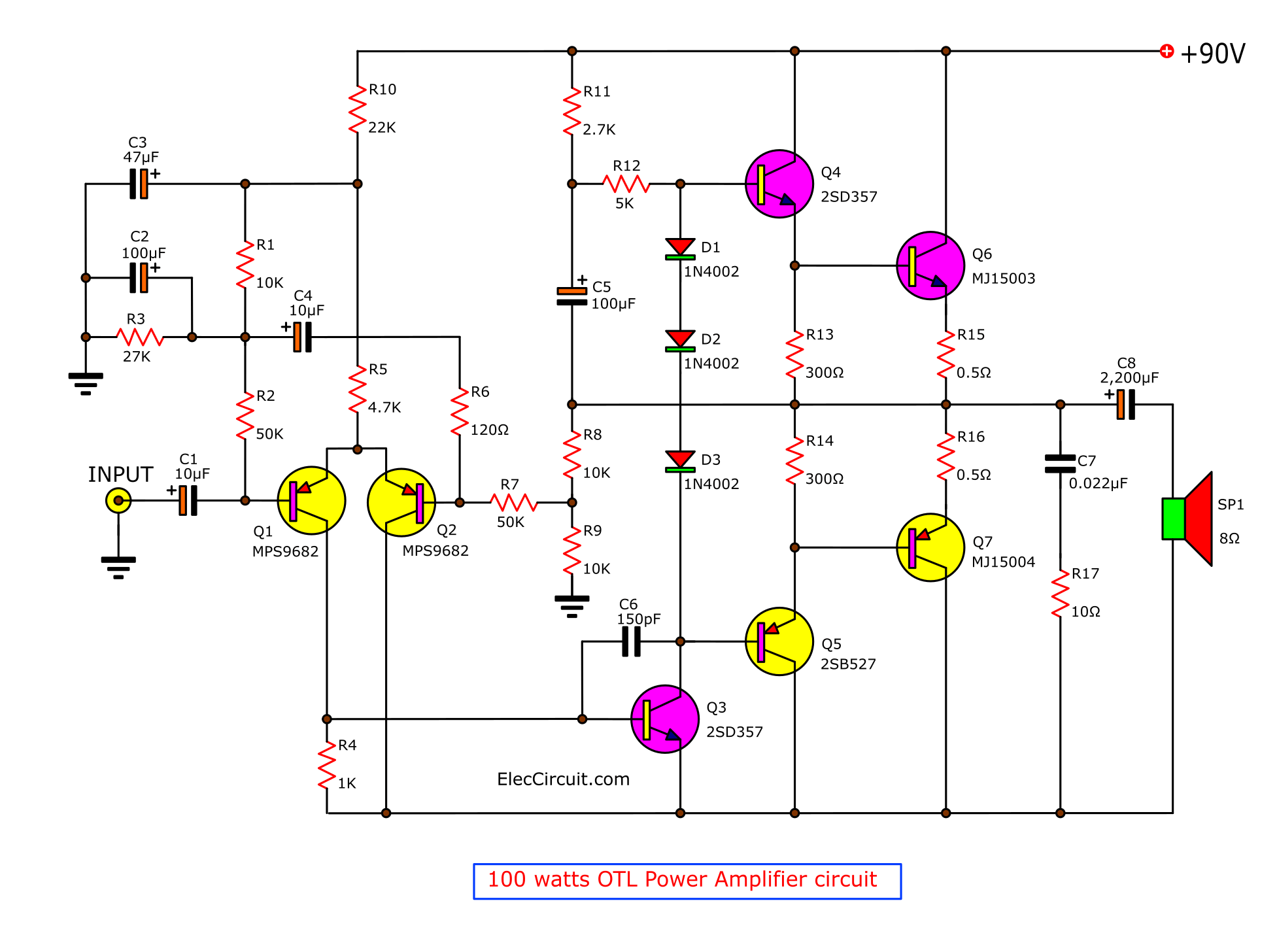
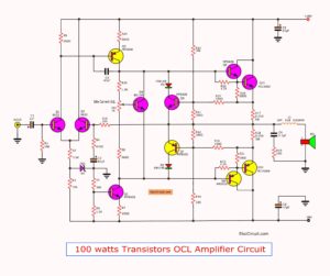
Figure 1: 100 watts OTL transistors amplifier circuit
In first pair differential transistors. We use MPS9682. Then, the preamplifiers drive, Q3. We use transistor 2SD357.
And the dual transistor drive are 2SD357 & 2SB527.
For the dual power transistors, we use MJ15003 matched pair with MJ15004. So, they have a full real wattage to 100 watts absolutely.
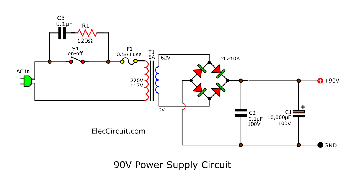
The 90V Power Supply
In figure next, this circuit we use the DC power supply circuit, 90 volts at 5A.
The AC voltage 62V from the transformer is converted by the Bridge diode rectifier to be DC90V voltage. Then, pass to the 10,000uF 100V Capacitor to filter to smooth DC voltage.
Build OTL amplifier circuit
First of all, we should get components as list below.
The Shopping Lists
0.5W Resistors, tolerance: 5%
R1, R8, R9: 10K
R2, R7: 50K
R3: 27K
R4: 1K
R5: 4.7K
R6: 120 ohms
R10: 22K
R11: 2.7K
R12: 5K
R13, R14: 300 ohms, 1W Resistor
R15, R16: 0.5 ohms 5W Resistor
R17: 10 ohms, 1W Resistor
Electrolytic Capacitors
C1,C4: 10uF 50V
C2,C5: 100uF 50V
C3: 47uF 50V
C6: 150pF 63V, Polyester Capacitor
C7: 0.022uF 63V, Polyester Capacitor
Semiconductors and others
Q1, Q2: MPS9682 PNP transistor
Some can find it. You may use BC557 (See this)
Q3, Q4: 2SD357
Q5: 2SB527
Q6: MJ15003, 20A 140V NPN, Power transistor
The Replace Part are 2SC5200 = NPN TRIPLE DIFFUSED TYPE POWER AMPLIFIER APPLICATIONS or,
2SC3856 = NPN Epitaxial Planar Transistor 15A 300V 130W Silicon Transistors
Q7: MJ15004, 20A, 140V PNP Power transistor
The Replace Part are : 2SA1943 = TOSHIBA TRANSISTOR SILICON PNP TRIPLE DIFFUSED TYPE or,
2SA1492 = PNP Epitaxial Planar Transistor 15A 300V 130W Silicon Transistors
D1, D2, D3: 1N4002, 1A 100V Diode
Note
This project is quite ancient. Now it also works well.
But when you will try to build a new generation still problems buying a transistor, sure.
Special instructions from a friend of mine.
On the transistor MJ15003 & MJ15004. Shape TO-03. Which is now hard to find.
I hope that friends many happy with this project. But do not forget about security. Check it carefully.
In Figure 3 is a PCB layout and positioning devices. In creating this project, be sure that the soldering is completed. The polarity of the diodes, capacitors electrolyzed is correct or not?
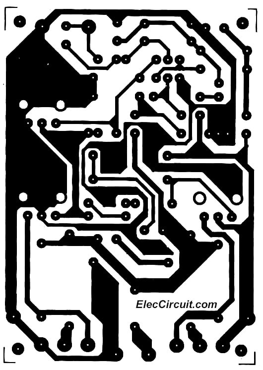
The Figure 3 is PCB layout.
Click to view large size

Setting and Testing
For safety, always complete your circuit before attaching your power to the circuit.
You should remove the power transistors before. Then, attach the probe of the voltmeter at a point between R15, R16.
If you are using a multimeter that is not auto-ranging, set it to the 100V range.
Then, add a power source to this project. The voltage must be between 40V to 50V.
But if wrong of these shows, the circuit will not work correctly.
To check the value of the equipment used to assemble the proper place for it or not.
Once you make sure it, so can be connected to the MJ15003+MJ15004 in the circuit.
However, need to make sure that the installation of transistors on a piece of the heat sink all that is good. Do not lose, or short-circuit with a cooling strictly prohibited.
Then, the input power into the circuit again.
Measure voltage is equal when does not connect the power transistors. Then Input the signal from preamplifier tone control or audio CD to hear a sample sound.
So the complete process of creating this project it.
Caution! This project needs to use the speaker protection circuit. Otherwise, your speaker may be damaged.
You may like these circuit, too.
Related Posts


I love electronics. I have been learning about them through creating simple electronic circuits or small projects. And now I am also having my children do the same. Nevertheless, I hope you found the experiences we shared on this site useful and fulfilling.
I want the full kit or pcb otl 100 watt amplifier,please tel me sir how can i get…pls reply me,
than k you
Hi,
I am sorry. I cannot sell this project to you. But If you want to build it. I believe you can do it.
Thanks
please specify the wattage value of all rasistance
Hi,
Please see this post again. I updated it now.
Thanks a lot, friend
it’s very old..ddddddd circuit.
good post!
Hi idea.
Thanks for your feedback.
Hi there I am so grateful I found your blog
page, I really found you by mistake, while I was researching on Askjeeve
for something else, Anyways I am here now and would just like to say kudos for a tremendous post and a
all round enjoyable blog (I also love the theme/design),
I don’t have time to go through it all at the minute
but I have bookmarked it and also included your RSS feeds,
so when I have time I will be back to read much more, Please
do keep up the great b.
Thanks for your feedback.
PLEASE HELP ME TO CONTACT MANUFACTURERS WHO CAN DEVELOP CAR AUDIO/VIDEO PCB & CAR POWER AMPLIFIER CIRCUIT FOR ME AS PER MY REQUIREMENT
Hi, Evin
I am very glad that you like the website, I hope you will visit often. I try to keep the site as well.
KUWE VOLTASE NE APA ORA KEGEDEN MASA 90 V DC, MBOK NJEBLUG TRANSISTORE KANG,WIS DIUJI COBA APA URUNG…?
Hi,
Please try it in English. I cannot use Google translate.
Did you see what you upload? The PCB plan and the circuit plan is different! Second: 90dc to much to the 2SD357. My opinion nobody do NOT do that cooker amplifier.
D357 transistor’s base connected to the ground in the PCB plan. Very interesting! The PCB is bad!!!
In pcb .overlay. D357 is printed reverse from base and emitter. But layout is correct.
helo..i want to ask something..could Mps9682 change mybe with another transistor..coz mps9682 are hard to find in my area..tq ✊✊
this otl circuit audio playing troughting voice whats the problem pls help me sir this my requst pls pls
WHERE WE CAN FOUND ITS CONTENTS
if i want variable current upto 60A with 12V then? what i have to do??
Hi Ecloud,
Thanks for your visit. Do you use DC to DC converter circuit?
Input is 12V to control the output is 0-60A?
Please tell me again. I not clear.
Can it be used with 4ohm speaker and powered by 80V?
Hello ventsislav Baev,
Thanks for your visit. I like your question.
Yes, You can use 80V power supply and a 4 ohms speaker. But it needs to be a higher 150watts rate of speaker.
Thanks again,
Apichet
can i give 12v to this circuit…?
Hello walasra,
Thanks for your visit. This circuit rate is designed for a 90V power supply to power output is 100watts.
If you use 12V power supply. This circuit will not work full power.
Do you want 100 watts output?
Thanks
Apichet
Circuit for amplifier using MOSFET 200w and above