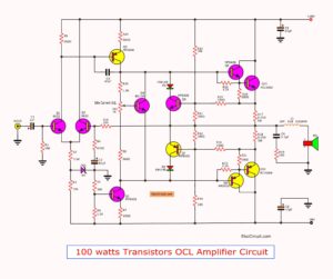
If you are looking for DC amplifier circuit. This may be one of choice for you. This is the DC servo amplifier circuit, OCL100W.
It uses MOSFET 2SJ162 + 2SK1058 Or MOSFET 2SK134 + 2SJ49 (To-3).
The output powers of 112 wats at Speaker 8Ω. And, Requires Power Supply +56V/-56V 4A /Ch.

For those who want to be satisfied, so fun. This series of 100W power MOSFET amplifier be able to you for sure.
It have responding of sound frequencies very well.
Invite you to consider this circuit project below.
How it works
See in the circuit. You will see that characteristics of the circuit is similar to the OP-AMP power circuit.
Because of positive input for the signal input. And the negative input for connecting a feedback signal.
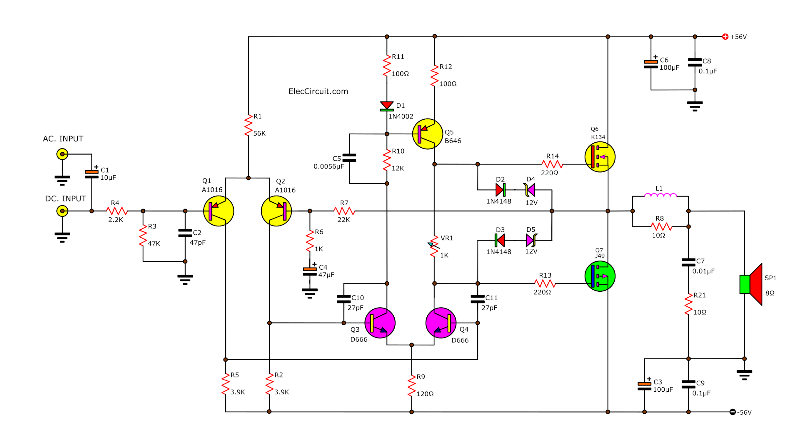
This circuit can work well, even at low frequencies alike DC signal. So, we may call it the “DC Amplifier circuit”.
Also, you may apply it to the servo amplifier.
Gain and Output power
The gain of this circuit depends on the R8/R7. From values in the circuit to has amplified rates equal to 22.
If there is an input signal size of 1V. So, the output voltage is 22V.
From Ohm’s law.
We can calculate the power output equal :
Power = (ExE)/R
= 22 x 22 / 8
= 66.5W at load 8Ω.
or = 120W at load 4Ω
So, if you want to output 100W at load 8Ω. We will need to enter the input signal is not lower than 1.28V.
Adjusting idle current
The transistor Q5 is constant current Circuits as the bias of output MOSFET. So, it can be adjusted by adjusting VR1.
It makes the circuits more good stability. Some called it the idle current.
The VR1 should be chosen carefully. For example CERMET.
Protection MOSFETs
At the gate of power MOSFET have the Zener diode to prevent the input signal is higher than 14V. Because MOSFETs will be damaged.
Recommended: High MOSFET Power Amplifier
The MOSFET runaway thermal
The advantages of the MOSFET power amplifier circuit. We know very well is preventing overload by itself.
How?
When the over load. The MOSFET is higher the temperature. But resistance of the MOSFET is also higher. (In normal transistors, the resistance will decrease.) As a result, the current through the MOSFET lower.
If we install the heat sink the appropriate size. Then, can be easily shorted output. But the MOSFET will not be damaged.
MOSFET Amplifier Power Supply
The most important factor, which will make circuits work to its full potential is the power supply circuit.
We suggest using the power supply separately, for each amplifier.
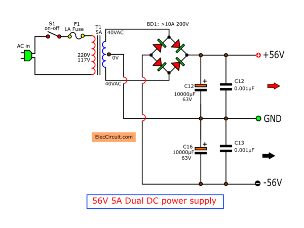
The advantage of this power is that it helps reduce cross talk and low frequencies as well.
Then, the transformer should be able to provide the current at secondary coil than 3 Amps (recommended 5A).
And, has voltage output at 40 Volts center trap as well.

How to build
First, prepare all equipment.
The shopping list
0.5W Resistors, tolerance: 1%
R1: 56K
R2, R5: 3.9K
R3: 47K
R4: 1K
R7: 22K
R9: 100Ω
R10: 12K
R11, R12: 100Ω
R13, R14: 220Ω
R8, R21: 10Ω 1W
Ceramic Capacitors
C2: 47pF 50V
C10, C11: 27pF 50V
MKT, or MKP Capacitors
C5: 0.0056uF 100V
C7: 0.01uF 50V
C8, C9: 0.1uF 100V
Electrolytic Capacitors
C1: 10µF 25V
C4: 47uF 50V
C3, C6: 100uF 100V
Semiconductors:
Q1, Q2: 2SA1016 or A872, -100V 50mA, PNP TO-92 Transistor
Q3, Q4: 2SD666, 80V 50mA, PNP TO-92MOD Transistor
Q5: 2SB646, -80V 50mA, PNP TO-92 Transistor
Q6: 2SK1058( To-3P) or 2SK134 (To-3) N-channel Low-Frequency MOSFET
Q7: 2SJ162( To-3P) or 2SK49 (To-3) P-channel Low-Frequency MOSFET
D1, D2, D3: 1N4002, 100V 1A Diodes
D4, D5 12V 1W Zener Diodes
Others
PCB, Transformer, and power supply circuit, etc.
To build, just install the components as the proper circuit layout.
See pinout of these components in this circuit
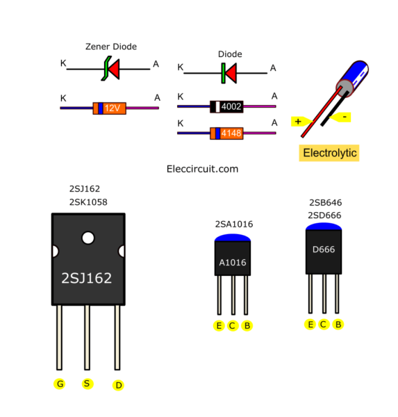
One thing to be extra careful about is installing the MOSFET on the heatsink. Do not short-circuit absolutely with the heat sink.
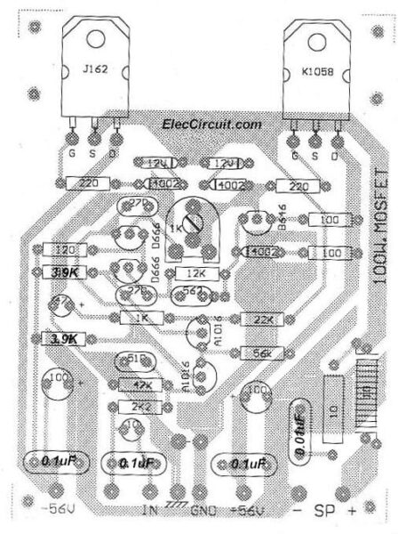
The PCB of 100 watt DC servo MOSFET amplifier
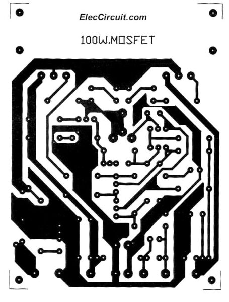
The Copper PCB layout of 100watts DC Servo MOSFET Amplifier
And See components Layout
Caution!
This project needs to use the speaker protection circuit. Otherwise, your speaker may be damaged.
Setting & Adjusting
When sure that everything is ok. Then, try to apply the power supply to this circuit. Without connecting the speakers.
Next, use a voltmeter to measure the voltage at the speaker. It needs to be no voltage or zero volts.
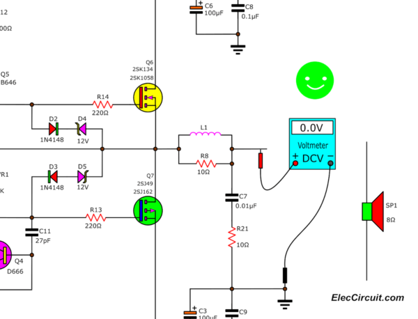
If it is not shown that the circuit failure at any point exactly.
Soldering is key
And most important, it should not be overlooked is the soldering, especially. Beginners usually soldering is not good enough.
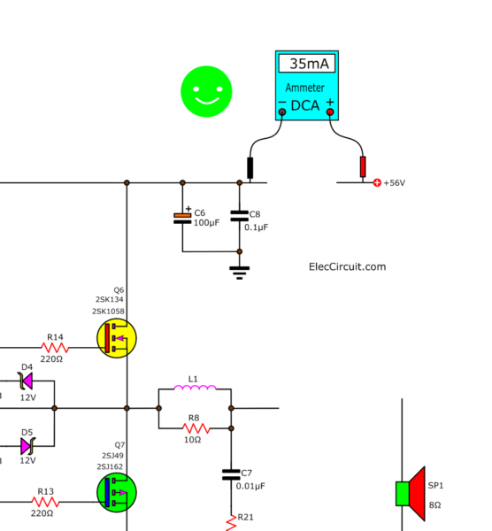
When the output voltage have been zero. Then, the next step is to adjust the Idle current for this circuit. Connect the Ammeter at the positive terminal. And, then Adjust VR1 at only 35mA is enough.
The ground is best
For installation into a metal box, just like a typical high watt amplifier circuits. What needs to be careful, is to install ground.
If we installed it incorrectly. It could easily cause the oscillator.
Remember
The ground of input and output circuit. We should separate lines and the ground at the same point.
For the PCB of this circuit, the input and output ground have separate neatly.
And, the ground wire, especially output and the power supply, use a large, durable power more than 15A.
See the input that enters to this circuit. We can use both AC input and DC input, depending on the requirements. But usually, it is recommended AC Input is safer.
You may like these circuits, too.
- 200 watt MOSFET amplifier circuit class G
- Simple time Delay Circuit using MOSFET
- Make Simple 555 Inverter circuit using MOSFET
GET UPDATE VIA EMAIL
I always try to make Electronics Learning Easy.

I love electronics. I have been learning about them through creating simple electronic circuits or small projects. And now I am also having my children do the same. Nevertheless, I hope you found the experiences we shared on this site useful and fulfilling.
Olá, excelente post. Mas tenho uma dúvida. Qual o valor do indutor L1 e quais os valores da bitola e de voltas?
Sem esses valores fica inviável o projeto.
Hi,
L1 = 10 voltas de fio esmaltado AWG18 enrolado no proprio corpo do Resistor de 10 ohms 2 Watts.
Se preferir pode enrolar separada do resistor, num diametro de 10mm.
L1 = 10 turns enameled wire AWG 18 wrapped around the body’s own Resistor 10 ohms 2 Watts. If you prefer you can roll separate from the resistor, a diameter of 10mm.
[ ]’s
10k Pot has an issue it burns when adjusted to max voltage
and also when adjust down to minimum voltage abruptly. Please look
into it and email me with a answer Please & Thanks.
Hola.Alguien sabe donde tengo que poner las puntas del multimetro para ajustar la corriente a 35ma? Gracias.
Hello JoseM,
Thanks for your visit.
I just update this post please read again.
Thanks
Hello Josemanuel,
Thanks for your feedback. I am happy that you like this circuit. Oh…It is great.
Dear sir, many thanks for your circuit diagram,I have gone through entire circuitry with all the details given, I will assemble this amplifier, thanks a lot once again.Regards
Hello Phillip.D
You are welcome.
Thank you so much, designer. Good or charity (in some religions) sent to the designer of this circuit.
Please don’t forget to share with me the progress of this project.
Thanks
Apichet
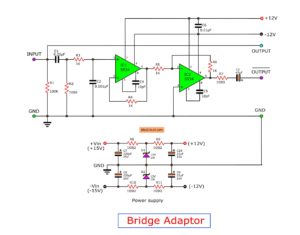
the bridge diode should be at least 120 volts (80 * 1.4142135– 112 volts.)
Hi My friend,
Thanks a lot. You are really great electronic person.
si me gusto gracias
Hello quillermo torres,
Thanks for your feedback.
And we need to thanks the designer a lot. We love him.
The PMOS is hooked up backwards in the schematic. People should be aware of this. The output for such an amplifier should be taken from the source of the PMOS not drain!
Very good sir you amp circuir…and very clear explain…thanks sir
Hello Shamal,
Thanks for your feedback. I am happy that you like it.
Have a great day.
PS. Thanks to the designer for this circuit, too.