This is a Big digital clock circuit without microcontroller for large size: 6 CM, cause can see clear on Very clearly in the range of 10 meters, even in the dark, because the display is easy to read numbers.
This projects use all CMOS ICs that easy to buy in store than the Cheap Digital time clock with alarm circuit by LM8560
The working principle
Look at Figure 1 is block diagram main principle of this projects. To begin with an 50Hz signal from AC line at our home, then it will be convert waveform from sinewave to digital signal in square of 50 Hz, then to feeds a 3000 counter circuit (with divided frequency inside).
Which this frequency 50 Hz, for 1 second will have the 50 cycle, so when we can count of 3000 cycle to must the times for 60 second. Which equals 1 minute digits there.
Related: Based time crystal clock generator circuit
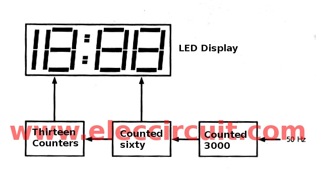
Figure 1 is block diagram of jumbo digital clock circuit.
Therefore, when the 3000 counter circuit counts wave of 3000 cycle (1 minute). Then it will send the signal to a sixty counter circuit to add the numbers in the minutes digits of the clock in one step.
Next recounts in 3000 cycle. Then send to the sixty counter in new continuously until to 59 digits, then will reverse into 0 number new.
In this time period will send signal to the thirteen counter add next step one and upto 12 digits, then will back to 0 number new then continues.
Read Also: Universal Digital counter circuit using CD4510 & CD4543
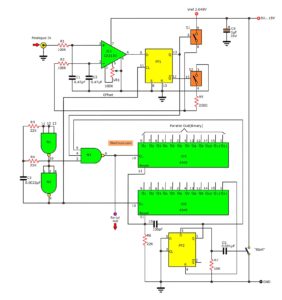
On base of principle we come to see real circuit in Figure 2 Diode (D1-D4), Capacitors(C1), Resistor (R2) and Zener diode (ZD1) acts as convert AC 12 volts is DC and The ability to maintain the regulated supply. The resistors R1,R3 and C2,IC1/1 are convert circuit to IC2.
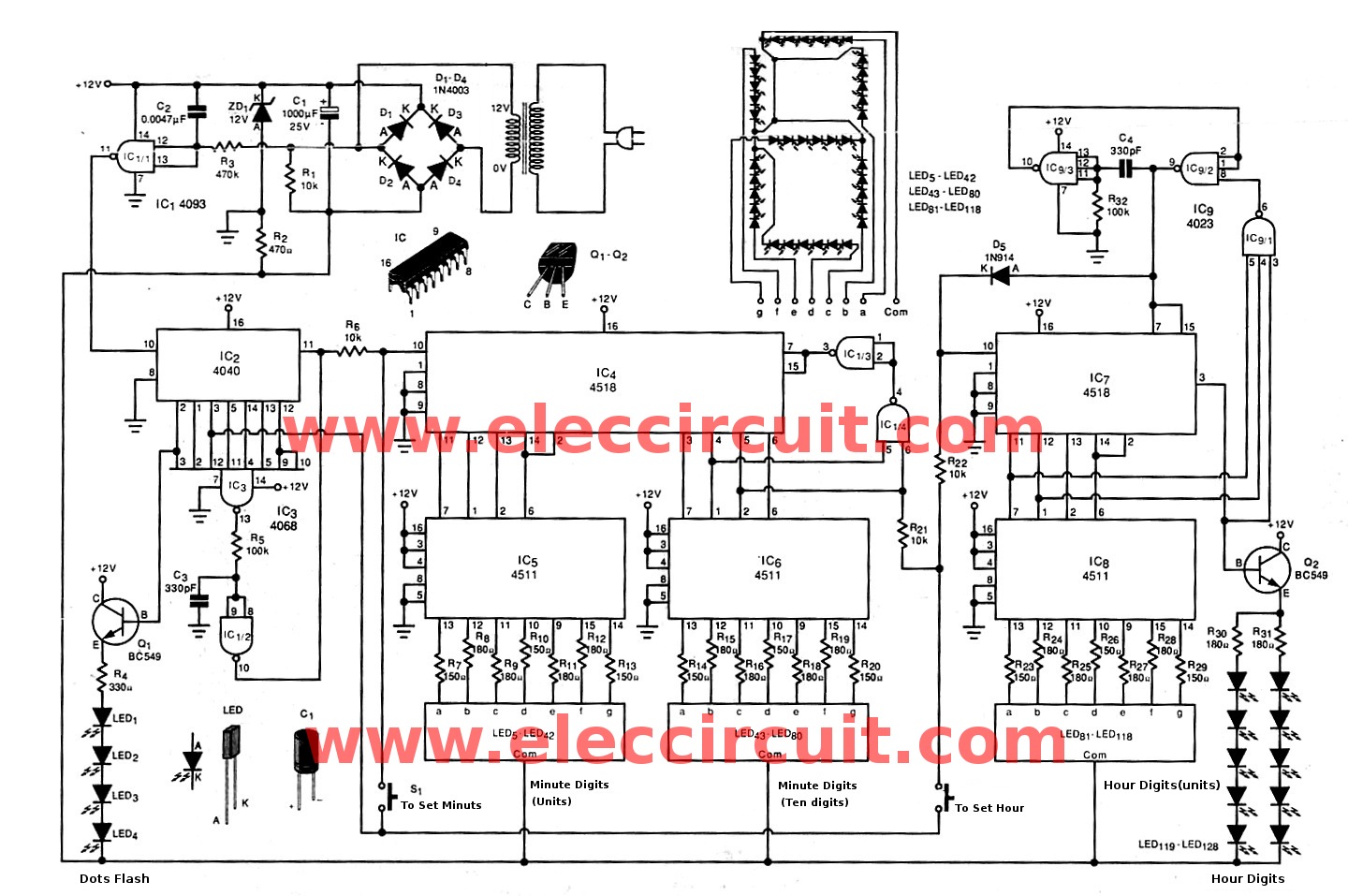
Figure 2 The Jumbo digital clock.
Which worked together with IC3 is the 3000 counter circuit. And divide frequency at pin 2 of IC2 will connected to base of transistor Q1, cause LED1-4 flash with frequency of 0.78 Hz
IC4, IC1/3, IC1/4 work together with the sixty counter circuit , next IC7, IC9/1, IC9/2, IC9/3 and Diode D5 work with into the 13 counter circuit.
Q2 acts as driver to LED119-LED128 display minute digits of hours( since 10,11 and 12 hour)
– Then IC5, IC6 and IC8 will decode on minute and hour digits to display clock number. Which use LED5-LED118.
– For each of the digit have Structure to be used as Figure 2. Which are seen as the LED on the main number to 38 pcs. Make large numbers more beautiful.
Here are a few related articles you may want to read:
- Triangle wave generator circuit with cmos inverter IC
- Random counter circuit with 7 segment display using basic digital IC
- 10 LED roulette circuit using TC4011-LM4017
Idea to builds
This project is very detailed. I recommend just creating a concept only.
Note: Because this project We have not created their own If you are interested in building this project. Require careful enough.
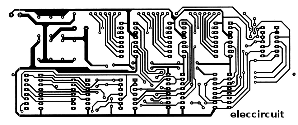
Figure 3 PCB layout of the controller circuit section
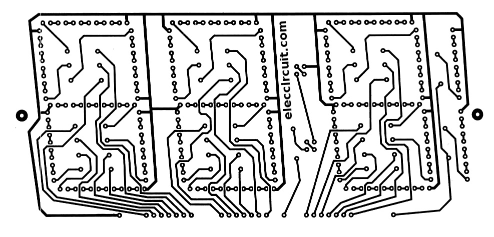
Figure 4 PCB layout of LED Display section
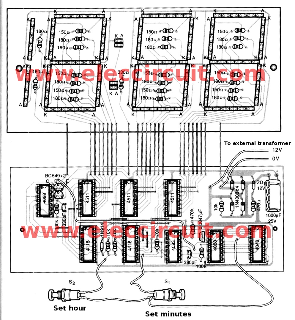
Figure 5 All components layout of this project
Want more brilliant ideas? Here’s how to get them through electronic circuits.
Components List
IC1: CD4093
IC2: CD4040
IC3: CD4068
IC4,IC7: CD4518
IC5, IC6, IC8: CD4511
Q1,Q2: BC549, transistors
D1-D4: 1N4003__Diodes
D5: 1N4148 Diodes
ZD1: 12V 500mW, Zener Diode
C3,C4: 300pF 50V Ceramic capacitors
C2: 0.0047uF 50V Ceramic
C1: 1000uF 25V, Electrolytic capacitors = 1 pcs.
LED1-LED128: LED: red rectangle form = 128 pcs.
Resistors 0.25W 5%
R1,R6,R21,R22: 10K
R2: 470 ohms
R3: 470K
R4: 330 ohms
R5,R32: 100K
R7,R10,R13,R14,R17,R20,R23,R26,R29: 150 ohms
R8,R9,R11,R12,R15,R16,R18,R24,R25,R27,R28: 180 ohms
S1, S2: Normally Open Pushbutton Switch
Check out these related articles, too:
- LM8365 alarm digital clock for beginners
- 2 Digit Simple CD4026 Digital Counter circuit
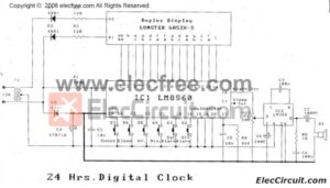
- LM8560 Digital clock circuit diagram with alarm
GET UPDATE VIA EMAIL
I always try to make Electronics Learning Easy.

I love electronics. I have been learning about them through creating simple electronic circuits or small projects. And now I am also having my children do the same. Nevertheless, I hope you found the experiences we shared on this site useful and fulfilling.

Hi,
Very interesting circuit.
Are the dimensions of the PCB?.
Thank you.
Hi,
I have created this circuit successfully, but there is one issue, the thirteen counter started from 0-12, but actual time start from 1-12 so no need of 0, I don’t know what is the reason to add 0 in hour digit so kindly inform me how can we escape this non using 0.
Thanks,
Naveed Anjum
SWG Technical Specialist.
Cell 0092-333-2224803
Hi, Naveed Anjum
Thanks for your feedback.
I am sorry I not also builds projects.
If this circuit work please share us.
Hi, Momename
Thanks for your reply, yes circuit is working absolutely fine, but its logic of development is not good, there is no required of 0 digit in hour segment, so unfortunately may I break it and remove my all components, if you want then I can show you working circuit, please share your email or anything else where can I show you.
Thanks,
Naveed Anjum
my e mail id is [email protected]…send me a correct circuit..
Hi,
How to use with a 7-segment
Please how many segment works for the minutes and hours?
thanks
thank for you
Hi All,
Thanks your feedback.
Dear Momename,
I am interested in big digital wall clock PCB, found you have the same. Is it possible to collect minimum quantity of the PCB or with the all parts of the circuits. If possible to deliver it to Bangladesh, then what will be the price of the PCB and the components and transport cost.
Mohammed Humayun Kabir Khan
Hai Naveed Anjum.
ITS not difficult solving your problem. Just see datasheet that PIN 11and 12 of Ic7 connected to Ic9/1 and ten, PIN 6 should be connected to reset PIN of Ic7, and must gives result to zero not one.
By the way i wanna know why Ic9/2 and Ic9/3 present in the circuit. Mau little bit wrong though not significant
Okay Naveed Anjum, what ia different of Ic4 and Ic7, try to be unfunctioned Ic9/2 , remove c4 330pf and connect PIN 1 and 2 to PIN 14, hence Ic9/3 act as not, then please try. If cant, more action is then remove D5 1N914. If cant, please discuss using datasheet and ask Yahoo. If you do it let me know at SMS or WhatsApp 0812 7049 2810 and 0896 2493 5815 indonesian celluler.
Please send me a correct diagram. I really want to built this circuit. My Email is [email protected] Thanks
Assalam o Alaikum
I am a school teacher
i need the digital circuits for amusing students
Hello Muhammad Azhar ul Islam,
Thanks for your visit. Your career is great.
I will set up a study center to teach children as well.
But now it is still beginning its construction.
I think the kids would like to play games.
We may be able to use digital circuits to make games.
But with truth these circuits, I haven’t tried to create it myself.
Therefore cannot confirm that does It worked?
https://www.eleccircuit.com/coin-toss-electronics-using-ic-ne555-cd4017/
https://www.eleccircuit.com/fun-electronics-circuits-that-will-improve-your-skill/
In the future, I will make these circuits for the children to play as well.
Sorry I could help you a little.
But I believe You are talented and do it for the kids.
You can do it for sure.
Thanks again
Apichet
Sir, I would like to build this wall clock, please may I have this working schematic diagram . Thanking you in advance.
Thanks to that you are interested in this circuit. We are sorry! now we can not rewrite it. It is on our list to do, soon. If you can wait for us, you will get the full circuit working with this working schematic diagram.
Have a great day.
🙂 Apichet and my kids
Thanks for your reply.
Hi there,
where i am, the power grid is 60Hz. what do i need to modify on the circuit to make the clock work on 60Hz instead of 50Hz?
what part do i have to modify to make it work on 60Hz?