It is difficult to make electronics easy for beginners and children. But I believe everything has a solution. So I try to make electronics easy. I am going to show you 5 fun electronics circuits and simple project ideas.
Are you up for it?

1# First times electromagnet learning for my son
My son likes to play electromagnet a lot like general children. And He read science books found content with magnetic. And, he did read science books found content with magnetic.
We take the 24 SWG coated copper wires turns on the diameter core of about 5mm is about 100 turns.
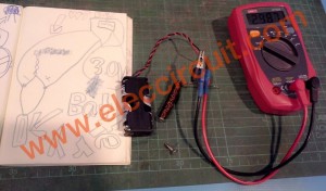
Then we scrape the insulated of copper out away. Next step apply the 3V battery and measure voltage it, the voltage low down to 0.5V.
The small screws that near it can be pulled to it same normal battery.
But this was not appropriate because the battery overheating Because of the current flow to the coil too much.
We should add the number of cycles and reduce the size of the copper wire to the smallest cause lower current operation.
2# Electro meter circuit using 2N3819 FET
Today we try to come to see the circuit checks the static electricity is simple. OR Electro meter using FET 2N3819. It can show the electricity bill dwells to follow the inventory that has an electric charge.

Such as plastic is hand, etc. By detect far get 30 centimeters. the value R1 give the meter can read the value 1mA. When lead load come to near an antenna very a little ? The value will that can read to is down in proportion. Request a friend has fun electro meter Circuit.
3# Sensitivity contest circuit
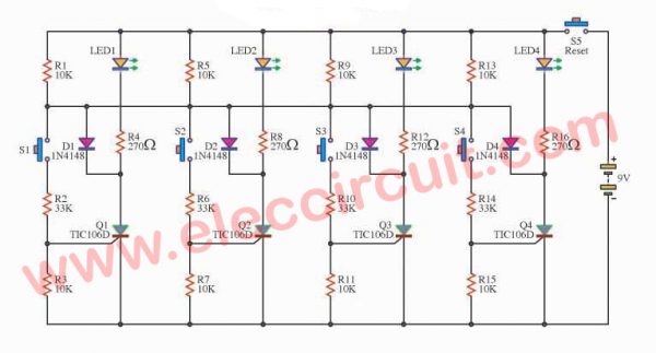
This is a challenge contest circuit sensitivity. in press. Can be played simultaneously by up to 4 people on one hit before. There are bright lights show the number of people who are pressing.
When raising the power supply circuit, and switch to either one up.
Suppose that the first switch S1, a current will flow through R2 into the leg to trigger the gate (G) of the SCR as a result, the flow between the SCR anode pin (A) and cathode pin (K). The LED1 is lit hold.
Working in this manner will allow only work one by one only. Because when the press sets a precedent to work, then send the output to lock the other later press against multiple performance metrics up. Until a new reset circuit, the switch S5 is press play to start a new one.
4# Concentration test circuit
This is the test concentration range, is ideal for a player to a game. Without a Net Amri alarm will be heard immediately.
Operation of the circuit is to use Q1, Q2, R1, R2, R3, R4, C1 and C2 together astable multi vibrator is a rectangular waveform generator (Square Wave).
It provides approximately 3 kHz frequency by a speaker with a piano sound So come out sharp tone.
When the test loop to touch. Don copper wire. If not, tapping each of the copper wire loop tests with speakers blaring piano So do not come out.
5# Simple Big Robot Toothbrush
Today, My son make a toy for younger sister. It is a Simple big robot toothbrush. The principle is very simple, It vibrates with movement, without direction and control. He took it to play with the cat great fun.
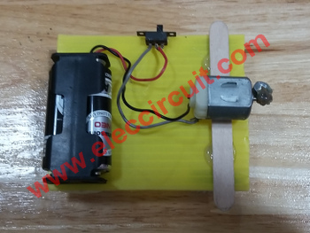
Figure 1 the Simple big robot toothbrush
He uses all the old parts
- The power source is the AA battery 1.5V x 2 = 3V. Because he uses a DC motor in toys. Which, it uses voltage about 1.5V – 4.5V.
- ON-OFF Switch, we use a small switch.
- All parts hold on the plastic board with glue.
The principle is very simple,
We use a toothbrush As wheels of the robot, as Figure 2
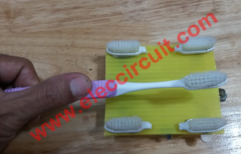
Figure 3: Vibration from the rotation of the motor.
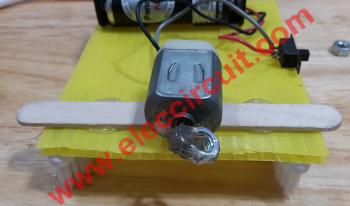
Which brings us to the female stainless nut to hold the spindle. Get it while it spins is a very centrifugal force. As warned by vibrating the mobile phone.
This project make the simplest toy it is not very good. It will be the next version soon.
6# Strength meter circuit using IC741
This is strength meter circuit that it can test we strong, by catch 2 metals. From that time squeeze meet. It will make LED stick bright arrange prevent according to one’s ability of squeezing the metal. The work of the circuit uses our body is formed lead the electricity changes to reach in the circuit.
The Circuit diagram of Strength meter
How working of Circuits
Which perform a temple resistance of the body. If we press wildly low resistance value make LED stick a lot of bright. By this circuit gives op-amp IC741 arrange each for other compare with voltage. In each the level of the intensity. We can stand the rapidity done to a turn VR1 and have LED Display 4 band. All in each band have IC741 detect voltage get and VR help fine the rapidity again the step. The detail is other , see in the circuit adds.
Not only that see these circuits
GET UPDATE VIA EMAIL
I always try to make Electronics Learning Easy.
Related Posts

I love electronics. I have been learning about them through creating simple electronic circuits or small projects. And now I am also having my children do the same. Nevertheless, I hope you found the experiences we shared on this site useful and fulfilling.
