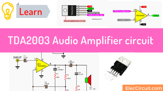
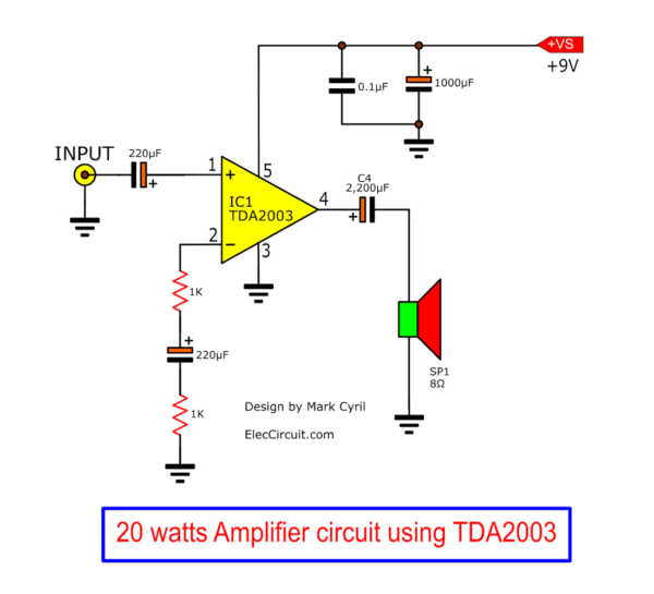
See, this is a TDA2003 amplifier circuit, a popular IC from SGS Thomson. Why we should use this? It is the normal operation of the integrated circuit, the music amplifier for car audio radio sound. Which uses a supply voltage from a 12V car battery. But this circuit is adapted for use in a home. By changing the power supply voltage to 18V.
So, this IC can easily deliver 10W to a 4Ω load speaker.
Read also: TDA2004 – TDA2005 subwoofer Bridge Amplifier circuit diagram
Datasheet in short
Look at TDA2003 looks like TDA2030.
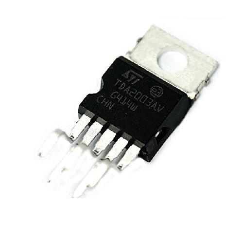
Cre photo: Exiron
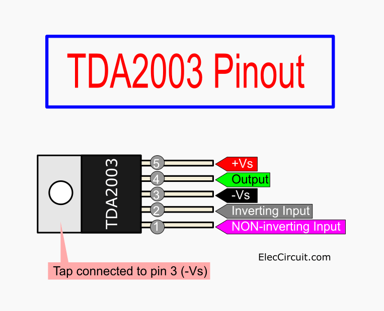
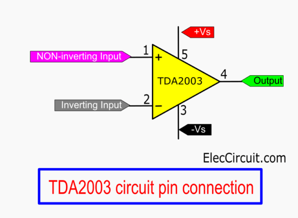
TDA2003 Pinout and symbol
Then, see its Circuit connection or symbol below.
We will see that it looks like TDA2030.
The maximum output power and relationship
Do you want to know the output power of this chip? If, Yes look at the graph below.
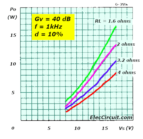
It shows the relationship between power out and applied voltage.
We will notice how the 8 watts only applies to a 4 ohms speaker. And, results when the applied voltage (VS) is about 18V.
We can use load is 1.6 ohms to 4 ohms speaker impedances.
Then, if we change load is an 8 ohms speaker, the power is practically halved.
This feature is a good side, right? It means that you can parallel:
- Two 8-ohm speakers
- Four 8-ohm speakers
- Two 4 ohms speaker.
They still get the same power. Or loudness emerging from each speaker.
We may place four 8 ohm speakers in parallel to output.
The volume is quite sufficient for the people in the assembly room and the volume control was only about half.
The clarity and bass response was exceptional. The figure distortion up to 5 watts is 0.2%.
In the datasheet, If you use 14.4V of VS.
In fact, the amplifier has very good figures up to 8 watts with a 2 ohms speaker and 6 watts with a 4-ohm speaker.
Once these limits are reached, the distortion level increases rapidly to 10%.
And at this level, the average person can noticeably hear that something is wrong.
How TDA2003 circuit works
See in the circuit below we will learn how it works. The output power is more than about 10 watts RMS.
And the TDA2003 can protect from damage and short circuits. When the load over.
And, Maximum Voltage of 28 volts. At the frequency response 40 Hz to 15 kHz.
The external components required for the power amplifier are either for feedback, decoupling or high-frequency suppression.
The amplifier itself is of a highly stable design with an enormous open-loop gain.
What is more? Let’s learn.
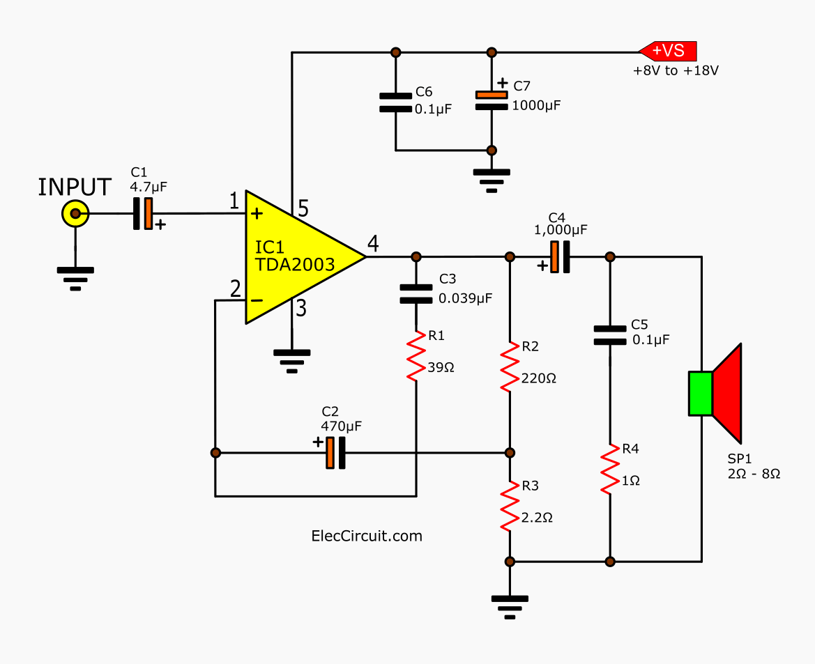
Here is step by step a process in each component.
Input capacitor
C1: The 4.7 uF electrolytic at the input. It is designed to AC couple the amplifier to a source such as a tuner or any audio signal.
The C1- 4.7 mfd input capacitor allows the circuit to operate without and DC shift occurring.
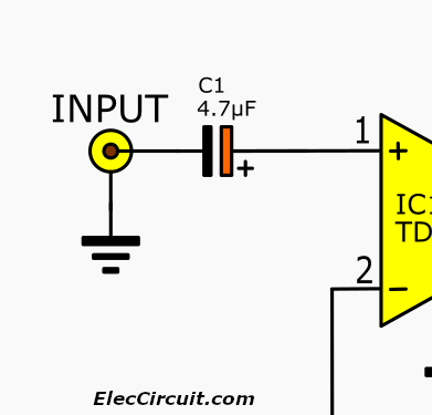
We may add the volume control to the input. And must be placed before the capacitor.
The power filter capacitor
See at the power rail has a C7: 1,000uF electrolytic and C6: 0.1uF capacitor across it.
The C7 is a storage capacitor for supplying high currents during peak passages. And, it also reduces the power supply ripple.
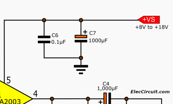
The C6 capacitor is quite important. It can prevent a form of oscillation from occurring at risky power supply impedance levels.
Frequency Cut-off
The C3: 0.039uF and R1: 39 ohms resistor form the negative feedback network.
The value of C is designed to set the upper-frequency cut-off.
And a larger value of C3 will reduce the maximum frequency.
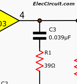
The R1 also sets the high frequency cut off point and if reduced in value, oscillation may occur.
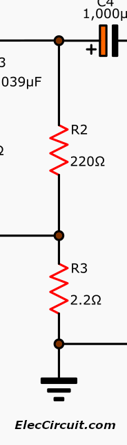
The gain setting
The actual gain of the amplifier is set by the ratio of the 220-ohm resistor and 2.2-ohm resistor.
If you like the TDA2003. And want to try it. See:

Read next: TDA2009 Amplifier stereo 10W | High Bridge 28 watts
Parts you will need
- IC1: TDA2003, 10-watt audio amplifier IC
Electrolytic Capacitor - C1: 4.7uF 25V
- C2: 470uF 25V
- C4,C7: 1,000uF 25V
Ceramic Capacitor - C3: 0.039uF 50V
- C5, C6: 0.1uF 50V
0.5W Resistors, tolerance: 5% - 39 ohms
- 220 ohms
- 2.2 ohms
- 1 ohm
- SP1: 2 ohms to 8 ohms Speaker
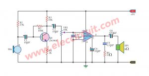
When entering the power supply 15 volts to the circuit. The C1 coupling audio signal through the VR1 to adjust the volume. Then sent to the C2 anti-noise DC input signal to pin 1 of IC. The non-inverting amplifier circuit is a non-return phase. This is the signal output pin 4, by a C5 enhances the stability of low-frequency response the better. And the noise will be dropped down to the ground by R4 and C6 before outputting to speakers. Another part of the output signal, which is fed back through C3, and R1, to enter the pin 2 inverting. To maintain a constant frequency response at-3dB. And if you want to add. The frequency response is to reduce the C3. The C8 is a filter file before the operation.C7 cut out noise from the supply. If you want a stereo amplifier,Is to create an additional set.
Read others: Thanks Credit: 8-watt amplifier using TDA2002 on Talking Electronics No.9
New design by Mark
Mr. Make saids”…
I found that the gain section limits the amplifier from performing truly. So I used a 1k resistor with a 470uf capacitor to ground from pin 2. I didn’t place any feedback resistor and it works quite well.
I am proud of his parent. He will have a good career future.
Thanks for sharing!
Here are a few related posts you may find helpful, too:
- LM383 Amplifier circuit, 7W, and 16W bridge amplifier
- Small IC Power Amplifier Circuits for speaker
- TDA2020 OCL HI-FI Power Amplifier, 20W to 80W
GET UPDATE VIA EMAIL
I always try to make Electronics Learning Easy.

I love electronics. I have been learning about them through creating simple electronic circuits or small projects. And now I am also having my children do the same. Nevertheless, I hope you found the experiences we shared on this site useful and fulfilling.

C3 in your schematic is 470 microfarad, which is way too large. A better value would be about 39 nano farad. Do the math, what do you think the gain will be with this capacitor? (Too low)
2SC2058 using adio amplifier circuit diagram
hi there and have a good time .
i made a circuit with tda 2003 . sound is ok but there is some noise like hummm.
i used a trafo 12v 3,5 A & a cap 6800 in power supply , shielded wires in preamp , star earthing in box .
please send me some words to resolve this problem . thanks .
Use a 1k resistor to ground on the audio input, play around with various resistors, until the hum has gone
Hi,
Thanks for sharing, your experience is great.
Have a good day.
We have a project on amplifiers for our finals and this schematic worked out fine and dandy! Cheers mate! 😀
Thanks for your feedback. I am happy to hear that.
ap ne capaciters k volt ni bataye
you have not mentioned capacitors volts
Hi. I am still in the process of studying electrical, however I found that the gain section limits the amplifier from performing truly, so i used a 1k resistor with a 470uf capacitor to ground from pin 2. I didn’t place any feedback resistor and it works quite well. I can share my schematics if allowed.
Hello Mark,
Oh. It’s great. You are a great student.
You learn and try and improve the circuit.
I like TDA2003, it is a good audio amplifier chip.
I quite an old man. How to add users to WordPress?
Is easier for you to send me the circuit? [email protected]
Thanks a lot for your sharing.
Apichet
Hi, I use this amplifier with an audio transformer instead of the speaker to transmit music over a long distance. The transformer has an 8 ohm primary and a secondary that brings the signal to 50 vpp; another audio transformer at the other end drives an 8 ohm speaker. Everything works fine but I would need to control the gain so that the amplifier output remains at a constant level regardless of the amplitude of the incoming audio signal. I was thinking of using a resistive optocoupler to change the gain but I have no experience on the correct way to use it, can you help me? Thank you.
Hi, is it at all possible and practical to use the TDA2030 IC in place of the TDA2003 IC?
I have not tried to compare them. But I will express my personal opinion. I would rather use TDA2030 circuit because it can provide up to 14W power at a power supply of up to 32V. However, TD2003 is sufficient for low power output at low voltage power supply.