Here is the Current booster circuit using transistors. Normally 78xx regulator series ICs can power max output currents of 1 A. Or in the common usage, it is only up to 0.6A. But we need more current up. You must buy a new one, like a 78H05 voltage regulator, LM350, or LM338, etc.
But it is expensive. How do you do? Read this may be alternative good for you. Don’t worry you can use the current booster circuit for 7805 (78xx).
The current booster circuit for 7805
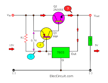
In this increasing Regulator Current or circuit, the power transistor is used to provide most current to the load, to maintain a constant voltage, by the little current still through the regulator IC intact.
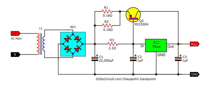
Let’s say, I want a 12V voltage regulator, and the current output voltage at 5A, I must to use an IC No. 7812 and it can take a transistor number MJ2955 or TIP2955. The input voltage is enough I think that about 20V, which voltage drop across the transistor is approximately 8V. And it takes about 40Watt energy, which can be calculated = Vce x Ic. When is this. We need a cooling pad for Q1, which is large enough, it is very hot, maybe cause damage.
If you want to add current to the IC 79xx or negative voltage, you can also easy to make, but simple NPN transistor type 2N3055 is only a number.
Want more brilliant ideas? Here’s how to get them through electronic circuits.
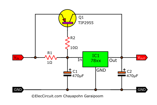
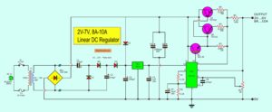
10A fixed regulated Supply using 78XX – MJ15004
If you have a lot of old pieces of equipment. You may build a 10A DC power supply circuit.
That be simple please, when I sees the equipment that him has had already. Then take this circuit see use 78XX integrated circuits. Have many the number and Transistor power number M15004 that can enhance current. Get tall arrive at 10A.
The important aspect is must use the Transformer that be appropriate give current 10A More than. And use C-Filter 10000uF sizes go up with. The detail is other see in the circuit has leisurely sir.
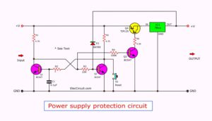
Increase current of 7805 with protection
But above circuit not have protection over load We need to use the below circuit!!
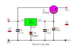
Sometimes we want to use. high current at a dc regulator 5v 3a. We can do this by using the voltage regulator IC1 positive constant number 7805.
The Q1-2N3792 and Q2-2N5956 of the circuit will serve to increase current for the IC regulator.
The R2 acts as the anti-saturation of Q12N3792 and Q2-2N5956. Without R2 will allow the two transistors to do not work. The output current can be from IC1 alone.R1 specify the bias current to IC1. And the current output of you against too much saturated with.
The C1 functions in the input power filter to smooth. And C2 serves to prevent interference with the pressure to payout (Vout).
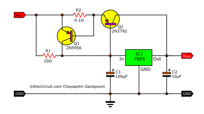
This circuit can help enlarge the current of the power supply circuit that uses an Ic regulator so well. you can use other IC 7805,7809, IC-7812, and IC7815. Q1 is BFX88 or Equivalent, Q2 is BD132 or Equivalent
Note: The section below inspired me to learn from here. Thanks
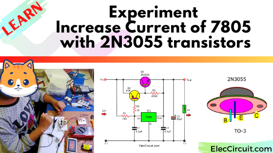
Experiment increase current of 7805 with 2N3055 transistors
Imagine you need a 5V 2A power supply to experiment with digital circuits. Only, you have plain components on hand. Is it possible to use those components? to create a circuit according to this problem?
We will find out which circuit layout provides maximum power and efficiency.
Let’s learn by experimenting with circuits.
Create the load
First of all, let’s get a good load. Why? It is very important for power supply circuit experiments.
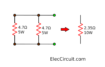
We think roughly if the power supply is 5V 2A, our load should have a resistance of 2.5Ω. Of course, the most economical way is to use ordinary resistors, with 10 watts or more of wattage. If we use 0.25W-resistor it will burn instantly.
But I don’t have a 2.5Ω 10W resistor lying around. So, I decided to put two 4.7Ω resistors in parallel. They become a new resistor with half the resistances, at 2.35 ohms. More importantly, it can withstand a power of up to 10 watts. It’s close enough to what we need.
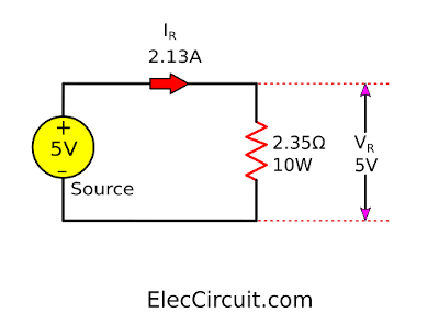
Then, connect it to a 5V 3A power supply, it takes around 2.1A of current, close to what we will need. And they seem not to be overheated.
Basic circuit 5V 2A using 7805 and 2N3055
See the circuit below, transistor Series Voltage Regulator. It’s simple and cheap. But it has low efficiency because we use Zener Diode to keep the voltage stable and the transistor can supply up to 2A as needed.
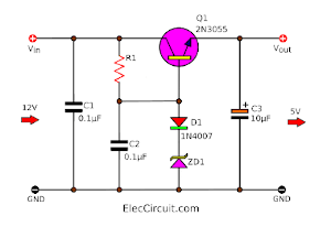
Next, we tried replacing the Zener Diode circuits with a 7805 regulator. Look at the circuit.
It’s much better. Because the 7805 works well, it’s specifically designed as a voltage regulator. But it can only supply about 1A of current.
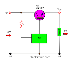
Put the 2N3055; This method might solve the problem. The output current of 7805 flows to a base of 2N3055. It will allow a much larger current to flow between the collector and the emitter.
This circuit quite worked. The output current is high up, according to the gain of the transistor itself.
However, we try connecting the load. Then, measure the voltage and current of the load. The result is unsatisfactory.
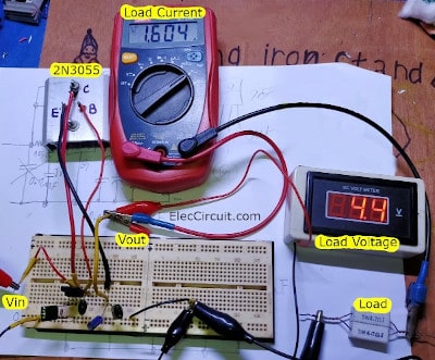
Note: you should read 7805 datasheet/ see pinout before assembling this circuit on a breadboard.
The load voltage is 4.4V. It is too low using a digital circuit. While, it is low current about 1.6A, too.
Why? I measure Vin, it is stable at 12V. Then, measure voltage the 7805’s output, it is quite lower to about 4V. The problem may be caused by 2N3055 or circuit form, unable to fully extract energy.
Oh…we only have 2N3055, don’t despair. Let’s find a solution.
When finding a problem, go back to the beginning. Let’s look at the structure of this circuit again. It makes it easier to understand.
We need a high gain transistor circuit. Which form circuit is best? Experiments are the best way to find answers.
Transistor circuit experiment
Prepare a load
It’s fun to find out the value of the devices. We intend to use the LED as a display device and the power supply is a 9V battery, for ease. It requires a limiting current resistor.
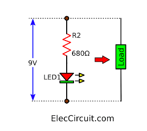
As the red LED 3mm uses 10 mA of current at 2V.
Thus we can calculate R2:
R2 = VBAT – VLED / ILED
= (9V – 2V) ÷ 0.01A = 700Ω
We use 680Ω 0.25W of the resistor.
Common collector NPN transistor circuit
Assemble the components as the circuit below. The LED glows.
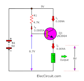
Then, measure the voltage and current. The load current is 0.009A, both IC and IE.
The load voltage is 8V. Some voltage across VBE is 0.7V.
In short, we call this a circuit pattern that common collector.
We prefer to use the power supply circuit working with the Zener diode as in the example above: transistor Series Voltage Regulator. It’s the form of the circuit that we use.
But there is a disadvantage, the voltage gain is less than 1 and the power gain is very low. So, can amplify the current less than we need.
See other simple electronic circuits
Common emitter NPN transistor circuit
Change the position of Load to connect the Vin and the collector of the transistor according to the circuit diagram below.
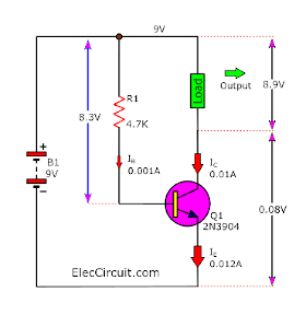
The LED1 lights up as before. Then, measure the current of the load. It is 0.01A exactly as calculated. And it gets almost full voltage as the power supply, 8.9V. It worked well. This circuit pattern is a common emitter.
It has a very high power gain but it is not suitable for this power supply circuit because we always need to connect Vout and Ground( negative).
What should we do?
Common emitter PNP transistor circuit
Use a PNP transistor, to reverse the voltage. I changed the transistor from the original 2N3904 to the 2N3906 Small PNP transistor. See the circuit below.
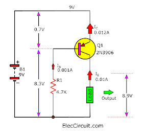
The load connected to GND and Output is similar to a normal power supply circuit. This circuit works fine, the LED is bright and has a current flowing through it, which is 0.01A exactly as calculated.
The form of this circuit is a Common emitter using a PNP transistor. It has a very high power gain just by changing the position of the R1 bias current to the base of the transistor.
But 2N3055 is an NPN transistor. How do we modify it?
Look at the Figure.
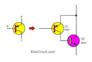
We place a small PNP transistor at B-C of a large NPN transistor. They work like one large PNP transistor. When B of Q1 is bias negative, Q1 conducts current. It allows a higher current from E to C of Q2. Turn the circuit to the other side.
Are you beginning to see ideas clearly?
- The current flows through R1 to 7805 regulators, it maintains a constant output voltage at 5V.
- Meanwhile, causing the bias voltage (VB-E) of Q1, it conducts current through B of Q2.
- This allows both Q1 and Q2 to conduct the current. Thus, a large current can flow through Q2’s C-E fully into the load depending on the gain of 2N3055.
Cheap 5V 5A voltage regulator using 7805 & 2N3055
Let’s start experimenting with the circuit assembly.
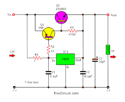
Look at the circuit below. The compete cheap 5V 5A voltage Regulator uses 7805 and 2N3055.
Can increase the current of 7805 with 2N3055 for Arduino? Read more
Interested components
The selection of devices to test is something that must be exciting. Sometimes its principle may not match the real devices. Because the quality of it may be different from the datasheet. So it’s a good idea to test it out.
- Q1: PNP transistors like 2N3906(TO-92), BD140(TO-139), BC327(TO-92), C9012(TO-92), etc.
- R1: It can be calculated from a simple formula: R1= 0.7/IIC; Note: IIC is the Bias current of the 7805 chip. Normally use about 0.012A, but I tried 0.046A with the highest efficiency.
R1 = 0.7V / 0.046A = 15 Ω - C1, C2, C3: These capacitors should be installed because they are very effective when the load is high current and reduces noise signals as well.
- All resistors use 0.5 watts.
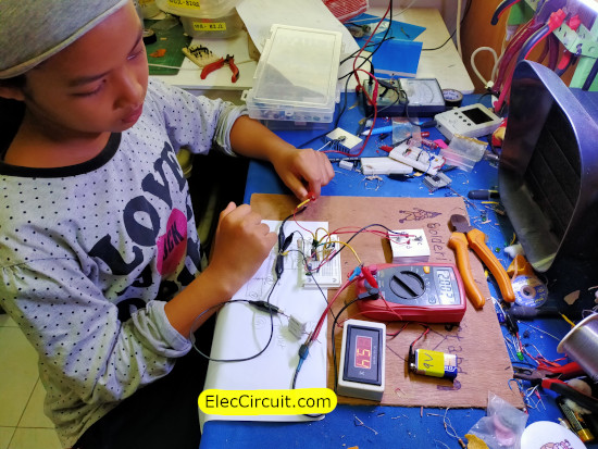
My daughter measures a load current of 2A and a voltage drop of approximately 5V as needed.
It worked well. What are the results of your experiment? Don’t forget to share some. If you have any comments or problems, don’t be considerate. Let us know quickly. we will learn together.
Download This Post
All full-size images and PDFs of this post are in this Ebook below. Please support me. 🙂
GET UPDATE VIA EMAIL
I always try to make Electronics Learning Easy.
Related Posts

I love electronics. I have been learning about them through creating simple electronic circuits or small projects. And now I am also having my children do the same. Nevertheless, I hope you found the experiences we shared on this site useful and fulfilling.
Hi, I am confused with the output voltage marking on the circuit diagram, it says +15V, whereas the topic / issue is only 5 volts.
Is this a typo-error? please do correct, as I like this simple to do/construct project for high current 5 volts circuit.
Can you tell me the other equivalent of 2N3792 transistor?
More power to your site.
Thanks in advance.
hi,i am confused with working of current boosting circuit and calculation that are used in dual polarity 15V power supply. what is requirement of over voltage protection circuit?
if its 7805 will be stabilized to 5v if you put 7815 it will be 15v. the transistors allow a higher current, than the IC delivers by its own.
How this circuit is working with a pnp transistor ? I know a circuit with npn transistor 2n3055 with base connected to regulator out and collector to input power and final out taken from emitter and ground. But how a pnp transistor circuit is working ? Please explain?
Hi,
It is very interesting. We are doing this. Please wait for about 1 week. a new update to explain its works on 2N3055.
I have also same question… did you find any answar..?
Please learn more: https://www.eleccircuit.com/experiment-increase-current-7805-2n3055-transistors/
Hello all…. Finally got the steps to increase the dc current in this page after a long search in internet…
But i have to know some more suggestions before i do any damage to my device….
Let comes to the point. I have a poly crystalline solar panel rated 5 watt, 18 volt max, 0.2A. I’m tried to build a solar phone charger and got partial result…. I.e my phone is charging at very slow rate….one percent charge takes nearly 40 mins….
So i need to increase the current to 1A from solar panel…… Will using the above circuit damage my phone or shall i move on to build.
If anybody design circuit for my solar mobile charger that would be thanks….
I am looking for a schematic for a good oscilloscope if you have any please can sen me
What are the voltages values of C1 and C2? It is rated 470uF, at what voltage?
Do you have a design for a 0-60VDC, 100A adjustable output, regulated power supply?
Can the necessary current like 10A can be achieved by transistors 2N3792 and 2N5956 alone without regulator IC 78xx? What is the purpose of the regulator IC 78xx.
Hello Premi,
We need to use a 78xx regulator. Because it helps to set the constant voltage at the output.
Thanks
C1 needs to be removed from this and all other copies of this schematic across the internet. Have you even tried out this circuit? Because of C1 (I know because I’ve tried) your output voltage will spike to Vin until C1 charges. Just remove it. There should be no capacitors between the resistor feeding the 78XX and ground. Put them before, put them after, but NOT IN BETWEEN.
Hello Robert Stoddard,
Thanks for your visit. And thank you very much For your useful comments.
Yes, I have never remove it. My teacher put it. I make like him.
It is good you tried it with yourself.
If I have free time I will try it too.
In my city, I had just had a great flood. My laboratory was damaged.
So I thought of building a new house. And all new laboratories.
I hope you will return to give good opinions. Like this again.
Thank you very much, can we be friends?
I see your child with all those parts and the board, does your child understand all?
Also, i do appreciate your efforts, i would like to contribute, let me know
Hello Arnold Palmer,
Yes, she was always involved in creating it. But she’s quite slow to understand it. I teach her in homeschool form. Learning only one electronics allows us to learn other subjects like math, science, etc, too. It is so great.
Yes, we are very pleased that you are generous to contribute.
Thanks so much.
Apichet and family.
I pleasure yours.
Thanks for your feedback.
I always loved electronics and how power flows these various electronic components.Just shows you are never too old too learn.I believe you learned from the cradle to the grave.
Hello Daud Williams,
I really love your text. Yes, Never too old for learning. Electronics make our life not boring and learned always to be creative. But we need a good magnifying glass, right? (Presbyopia) LOL. “I believe you learned from the cradle to the grave.” Me too!
Thanks
Apichet
Good explained
Hello Bharat,
Thanks for your feedback.
Power Booster for 78XX Series.!
Welcome to,
I have some comments on your drafts and would like to ask for your help. My goal is to design a stable 9V 2,5A psu for my custom project based on your work! I recently builded your original sketch with a toroid transformer (secunder is 12V/2.9A) but only with half results… So it works with 7809 instead 7805 and with a reduced R2 (original was 1K), but unfortunately a lot of heat is generated and this is dissipated by the TIP2055. Both the toroid and the graetz heat up quite a bit after some time. Also long tested the build and after two hours of loaded with a bulb with 2A they are all very hot! Another bad result is the voltage drop: without load its 9.2V, but with the loaded bulb its only 8.1V, which is not enough and not satisfactory.
Please help me optimize it to work on 9V output.
Thanks and keep teaching 🙂
Peter
—
Hello,
I recommend it based on my experience. You need 9V 2.5A Regulator circuit. Yes! You should use 7809, it’s easier for this circuit. But due to the nature of the Linear power supply, it will have high energy losses. We must pump the input voltage higher than 4V or Vin = 13VDC up. When using a transformer size 12VAC x 1.414 = 17VDC. But when there is a large load This causes the voltage to drop to approximately 12VDC., which may not be enough. I would like to suggest that you try increasing the filter capacitor size to 4,700uF to 6,600uF. This will increase the voltage.
Or try changing a 15VA transformer. It will make the voltage come out higher to 21V. When the load consumes higher current. Makes the voltage fall but will be greater than 15VDC.
In another case, you should use a good quality 2N3055 transistor. Because I used to use low quality transistors. Make the current decrease.
I hope this experience helps you. Thank you