This is cheap hearing aids circuit project. Or a small listen booster is a simple function. They are similar to the common small audio amplifier. Why use it? Imagine your dad is old. Sure, he hears anything weak sound.
How do you do? You are an electronics inventor, right? Yes, you can try to make a tool. To help him back to listen to great music again.
This project is small, use only one 1.5V battery. Using normally components you can buy in stores near you.
Let’ s getting to learn. The working starts with a preamplifier circuit. We receive audio signals from a microphone. Then, it increases a lower signal to a higher volume up before. Next, a power amplifier boosts power up again. To drive headphones to we hear that sound.
Is it easy? Yes, you can read more in deep.
Learn: Designing small signal amplifier circuit using transistor simply
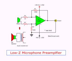
Dynamic Microphone Amplifier For Earphone
Look at the circuit below.
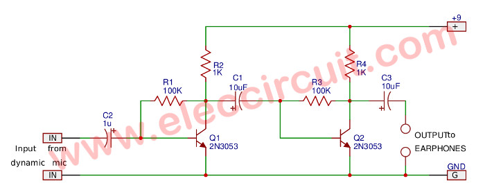
It is a simple two-stage transistor amplifier.
All of all, a dynamic microphone gets a sound to convert into a small signal. Then, the C2-capacitor gets only AC to two 2N3053 NPN transistors have a particularly high gain. Next, the higher signal comes out of C3 to an earphone output.
But this circuit is not suitable for true using. So, look at the second circuit below.
Related: Low noise microphone preamplifier circuit
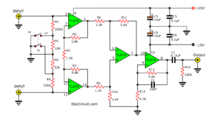
Hearing Aids Circuit Project
The specialty of this preamplifier circuit is an automatic level control circuit or ALC.
Which it will operate at a fixed control volume automatically.
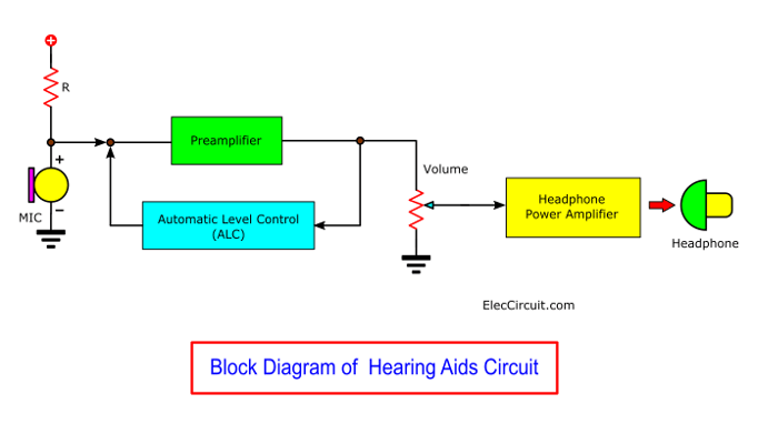
Suppose that the sound is very loud. This circuit will turn the volume down. On the other hand, if soft sound. It will increase the volume up. Make us hear all the levels. Both many and the less sound. And we can adjust the volume as needed. To set the volume to a level that is appropriate for each person.
Read Also:Active microphone preamplifier using LF356
How it works
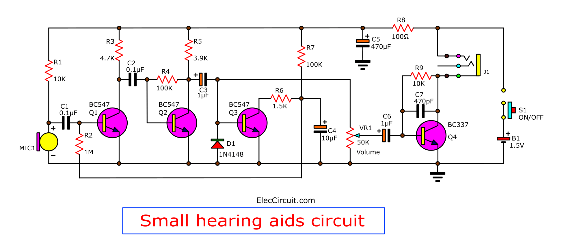
Look in the circuit below. It is a complete circuit of a hearing aids project.
Here is the step-by-step process:
Microphone preamplifier
Start with the microphone MIC1, condenser microphone. This MIC requires a DC voltage supply. So, It gets DC current by a battery through resistor R1(10K).
Then, a sound signal from MIC comes to C1- 0.1uF capacitor. It passes only AC to amplify into the base of transistor-Q1, BC547.
Which serves as a first audio preamplifier set.
The output signal at collector via C2 connected to Q2. It acts as the second preamplifier.
This is a very high gain. There are resistors R3, R5 are a load, the R4 is a feedback and bias base to Q2 runs.
Read first for beginners: How do transistor circuits work
Next, The signal via C3 to the coupling signal in two ways:
First way:
Automatic Level Control
To automatic level control circuit. It includes transistor-Q3. It makes a feedback bias current to a base of Q1 to control the volume of the amplifier.
Which this voltage occurs from a DC voltage by rectifier diode D1. This voltage will be filtered to a stable level before.
And a capacitor C4 delays a step of volume control, fast or slow. If small value makes the rhythm control up and down of sound faster. But if the value is high, it will slow the sound control.
Next, send a signal to the base of Q1 through R2
If MIC1 gets a loud voice. There is a many bias current to Q3. It causes a collector voltage of Q3 is lower. And, makes a voltage of C4 is lower, too.
This level volume control voltage will via R2 into the base of the transistor Q1. If the voltage is high (MIC1 is low volume) will have a bias current to the Q1 works more and louder sound.
In contrast, if the level volume control voltage is low (MIC1 is louder).
It would make current input to the transistor decreases. As a result, the audio signal will be reduced accordingly. Thus, the sound level has nearly the same all the time. Whether loud or soft.
So what?
Headphone Amplifier
Then, the signal flows through to a power amplifier circuit to drive headphones to hear.
They include:
Transistor Q4-BC337 increases a sound signal.
Potentiometer VR1 adjusts the volume.
Connect signals through the capacitor C9 to the base of transistor Q4.
And R9 resistor feedback a signal and bias to the transistor works in class A.
Reduce the gain in high-frequency range by capacitor-C7. To reduce noise and maintain the stability of the circuit.
The sound signal from the collector is driven through headphones connected directly with the power supply. The headphone is a load of the amplifier circuit. Use only dynamic headphones with an impedance range from 16 to 32 ohms.
Direct Current pass Load
While turning ON-OFF this circuit. We will hear the sound “thub”. It is normal for the output that uses load pass current to the circuit.
So, before and after use this circuit you should not listen to your ear.
And it is not good for the headphone. But this circuit use 1.5V 27mA or 1.3mW only. It is so low, safe for all parts.
How to makes and adjusting
This circuit is a small size. So, you can build it easily on the Perforated PC board. Sure some this normal PCB look at the image below.

PCB layout for build this circuit
Parts you will need
0.25W Resistors, tolerance: 5%
R1, R9: 10K
R2: 1M
R3: 4.7K
R4, R7: 100K
R5: 3.9K
R6: 1.5K
R8: 100Ω
VR1: 50K (A) Potentiometer
Ceramic Capacitors
C1,C2: 0.1µF 50V
C7: 470pF 50V
Electrolytic Capacitors
C3, C6: 1µF 50V
C4: 10µF 25V
C5: 470µF 16V
Semiconductors:
Q1,Q2,Q3: BC547, 45V 100mA NPN Transistor
Q4: BC337,45V 800mA NPN Transistor
D1: 1N4148,
Others
Headphone
B1: 1.5V battery
S1: On-Off switch
Check out these related articles, too:
- Dynamic Microphone Preamplifier circuit
- Dynamic and electret condenser microphone preamplifier
- A Microphone From Normal Speaker
GET UPDATE VIA EMAIL
I always try to make Electronics Learning Easy.
Related Posts

I love electronics. I have been learning about them through creating simple electronic circuits or small projects. And now I am also having my children do the same. Nevertheless, I hope you found the experiences we shared on this site useful and fulfilling.
This sounds like a great project and it will be extremely effective in many ways. Keep up the great work. Thanks for sharing! – Hearing Aids Colorado
Thank for sharing this interesting project.
A question… What are the technical specifications of the mic? Voltage, etc…
(Sorry but english is not my first language)
Thanks in advance
@Nicole Renee
Thanks for your encouragement.
I was very happy. You like this project.
@Jose M
You welcome.
My English is poor,too.
We same English not well.
But we love hobby electronic like you.
Thanks a lot.
Nice project.
I was wondering if i could replace the MIC with an input audio jack for an mp3 player so that i can have fix volume from varying mp3s volume?
what software you are using in drawing of schematic,pcb pls inform
thank u sir,, v nice project,, almost i have done it…. (y)
So, the voltage supply is just 1.5V, not 3V? Because I see 2 “1.5V” in the schematic but in figure 2 the battery is just 1.5V.
..just verifying, thank you~ (^^,)
do you have a block biagram of ths? just asking :))
can you show the connection in the bo J1 ie the jack connection box.please help me with a quick reply??
Will this work? the headphone connection block diagram please?
Hello 😀
I’ve finished it for my projeeeect~
AND IT WORKS GREAT <3
Thsnk you for posting this :))
I would've wanted to leave a picture of the final thing with packaging but oh well….
again, THANKS!!
I’ve finished it for my projeeeect~
AND IT WORKS GREAT <3
Thsnk you for posting this :))
I would've wanted to leave a picture of the final thing with packaging but oh well….
again, THANKS!!
hey Aethel. can you please help me in the connection of jackbox.please help
what is operating frequency this circuit?
please help me with quick reply.
thanks for sharing this kind of project,i try to make this for myself,more power!
Hi,mel
Thanks a lot for your feedback.
Plz someone help me in connection of this circuit on pcb……..plz
Pls some help in the connections of pcb!! Immediately….
Pls guide us to connect jumper and jack sacket …….
Plz help me…..
In the connection of d ckt on pcb.plz……immediatly
spear detail want immigeat
to detail
please send me the schematic and pcb board,i want to build it as a gift to my father,,,pls reply if possible immediate
thanks
Hi spyru,
Thanks for your feedback.
I cannot send you schematic and PCB board.
GOOD job for your father.
Hi,
what software you are using in drawing of schematic,pcb and the 2D view
Hi Spyru,
Thanks for your feedback.
Long time ago, I use illustrator and corel draw
Now I use the Inkscape and the gimp.
wow,you have great work,,,
good job
anyway,i have been design the circuit in cadsoft eagle…
can u plzz give me the design of the circuit.
This is a super project. I built one for my Dad for his birthday. Most of the parts you can get in the USA from RadioShack. The transistors I got on eBay.
on a project hearing aid device
help out circuit please
For the science fair in our school, we are trying to make a hearing aid which could work with an app that would control the volume, is there a way for that to happen? We have not yet built it but the hearing aid seems simple to acomplish. Great job!
hy its so good…..keep the fire burning
Hello,
I tried your circuit and it works on the breadboard,
But when i transfered it into PCB i can only hear static and noise ,i all the connections are ok and i already replace the mic with a new one ,what do you think is the problem im missing?
Thank you
Im using a 1.5V DC source
Hello.
First of all thanks fo the circuit. I had done the circuit in a breadboard n had got output also. But the problem is that the audio output is very faint as if no amplification takes place. I had replaced 1.5v source with 9v battery and i had replaced 1uf capacitor with 0.1uf capacitor(the one in between two bc547-middle part). Could point out what might be the mistake.
Thanks in advance.
I’m getting a lot of noise in the output. Any tips to reduce it?
Hi Biral
I am very glad that you build this project.
This circuit is adjusted too high sensitivity. There may be noise.
I believe you should check everything well. And you are not a beginner because in this circuit the creator needs to have enough electronic skills
what software you are using in drawing of schematic,pcb and the 2D view
We have drawn it with the Inkscape freeware. It looks like the Illustrator.
Hello, thank you very much
But why is there so much information error?
The parts list does not match the map
Example of resistance
R1= 10k or 470 k?!!!
R1,R4??? R9???
The list of nominal parts of the diode is not listed
Hello Mousa
Thanks for your good advice. You are a great person.
I just update now.
Thanks a lot
Apichet
Hi
thank you very much
from your attention
I’m glad to do it.
Another question
Do you have a more advanced circuit?
Smaller and more professional
Is it possible to use IC?
I am sorry to tell you. Now I do not have the circuit that you want.
Next time I will send you that circuit by Email subscription.
Thanks
Apichet
Hi
One Question:
Capacitor C4 is different
In schematic design and Parts you will need:
which one is correct?
10µF 25V or 1µF ???
Yes, I just update now. Thanks
please guide me
I assembled the circuit
But I have noise!
Can you guide me to fix the problem?
I am sorry to help you. Because I never built it. But I believe in you. You can do it.
Thanks
Apichet
Hello, can I connect to a cellphone to record with app?
Hello Francisco,
Thanks for your visit. I am happy that you are interested in this circuit.
But honestly. I have never built this circuit yet. So don’t know It works fine. As you want or not?
However, I believe you are a brave person. And always keep on learning electronics. You can definitely do it!
In my opinion. This circuit has a very weak output. You may be able to connect directly to the microphone of the phone.
If you try and have any results. Please share with me, thank you very much.
Apichet
I was looking for this information relating to the cheap small hearing aids project. You have really eased my work by posting this article, loved your writing skill as well. Please keep sharing more, would love to read more from you!
Hi, and thanks for the schematic.! Could you/someone help me adding a 300-3000hz bandpass filter, to only let human voice frequencies through? 🙂
Hello Henrik Johansen,
It is a good idea. It’s interesting. I want to know too.
hi;
so many words!
anybody to have made it?
result?
thank u
kurdistani