Voltage to Frequency Converter Circuit
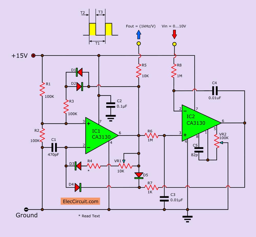
See idea: Voltage to frequency converter circuit use CA3130 OP-Amp, that linearity Of changing up to 0.5% and Temperature coefficient. Read more
See idea: Voltage to frequency converter circuit use CA3130 OP-Amp, that linearity Of changing up to 0.5% and Temperature coefficient. Read more
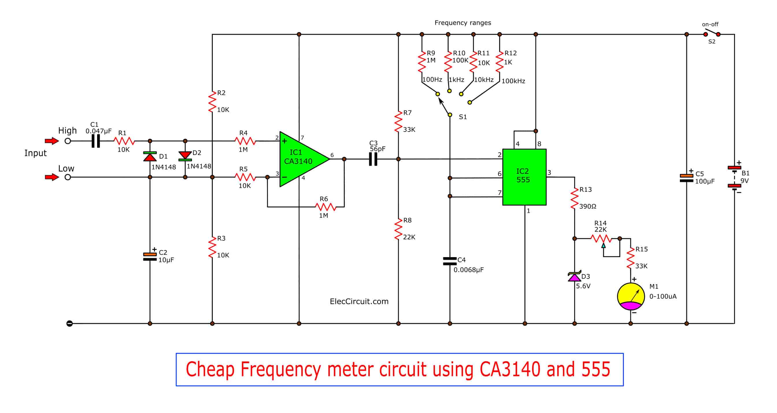
The electronics are still used to use a frequency generator circuit beuause It is important. And are used a lot in electronic circuits, both sine, square wave and more. In every time related to the frequency. What that we want to know is how much frequency.For laboratory common standards. We have many tools available to … Read more
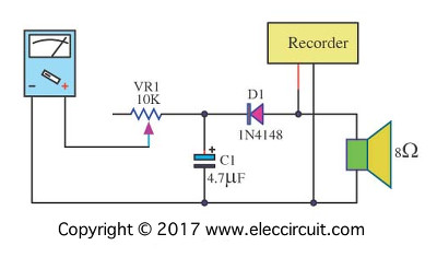
Let’s use two simple Analog VU meter schematics. If we take the amplifier connected to the speakers. It is very dangerous.If your amplifier has a higher power than the limits of the speaker. It may make a very bad sound. More important is the speaker and amplifier may be damaged.These circuits may help you! Simple … Read more