Here is two Low noise microphone preamplifier circuit. Which is simple circuit but high quality sound,includes devices that are selected very well.
This circuit can be used to all normal microphone, for example: the dynamic microphone of Europe zone that has impedance of about 200 ohms, the Japan microphone has impedance of about 500-600 ohms or others higher impedance microphone.
This circuit have 2 model are a balance Input Pre Microphone Amplifier circuit as Figure 1 and an Unbalance Input pre Microphone Amplifiers to can choose as you needed.
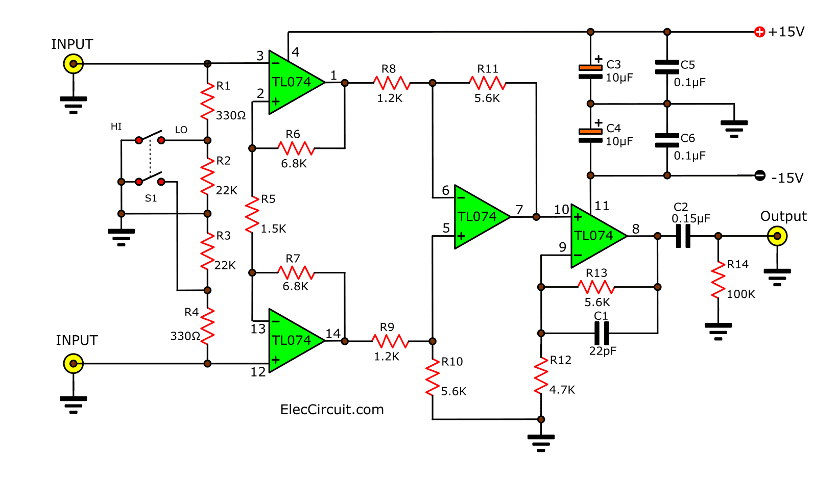
Figure 1 Balance Input Pre Microphone Amplifier circuit
How it works
Balance Input Pre Microphone Amplifier as Figure 1. The input signal will be sent to pin 3 and pin 5 of ICs, to increase signal. And send to pin 9-10 of IC3 that act as the differential amplifier. Thus, noise signal and various hum will be rid go away.
The output from IC3 will be increased again with IC4 to get the output signal as need.
The second section, the unbalance input as Figure 2 will see that the simple circuits by have two low noise ICs to connected together as the amplifiers circuit from microphone to high amplitude as need.
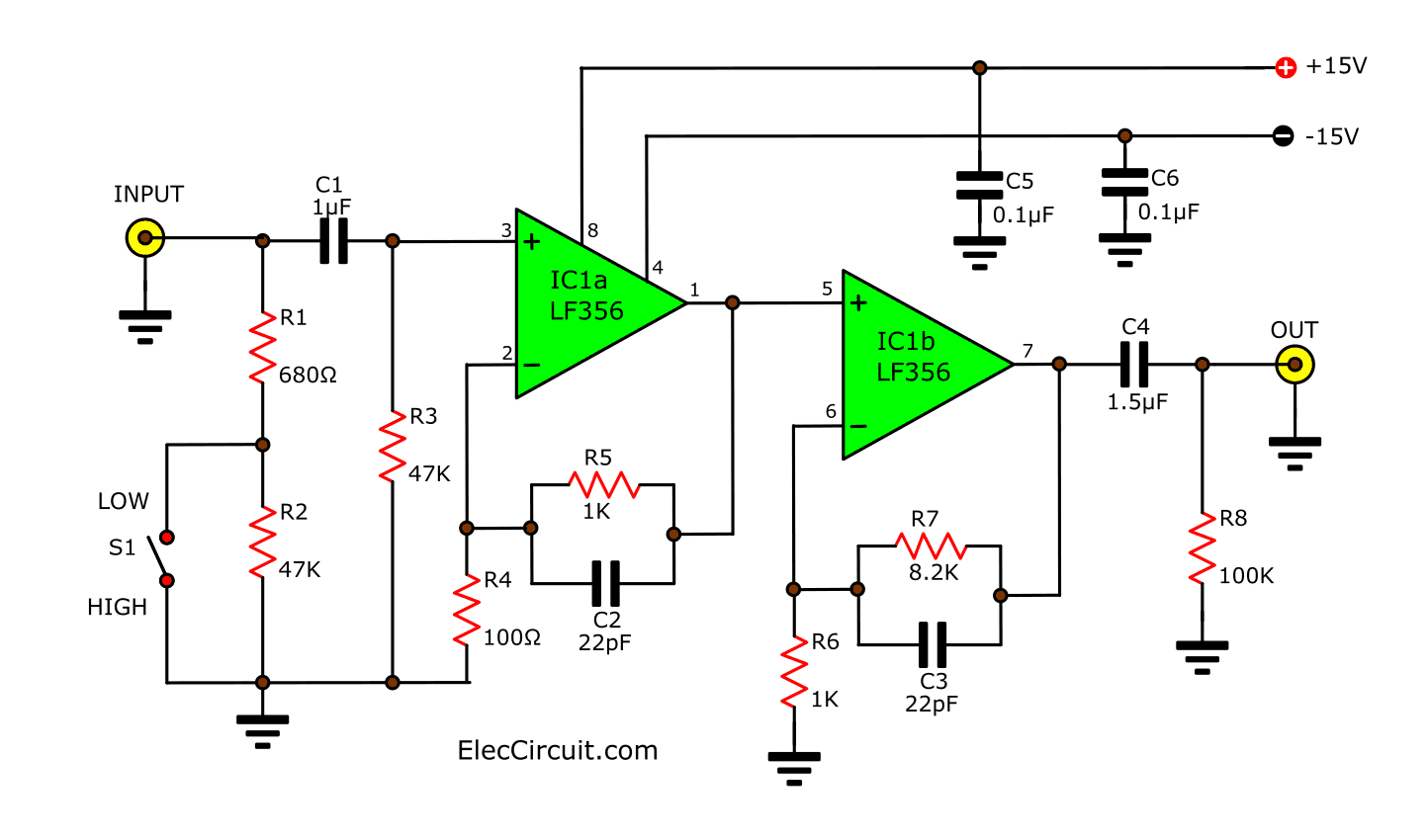
Figure 2 Unbalance Input low noise pre microphone amplifiers
How to builds
You Just assembling equipment to the PCB correctly.
As Figure 3 and Figure 4
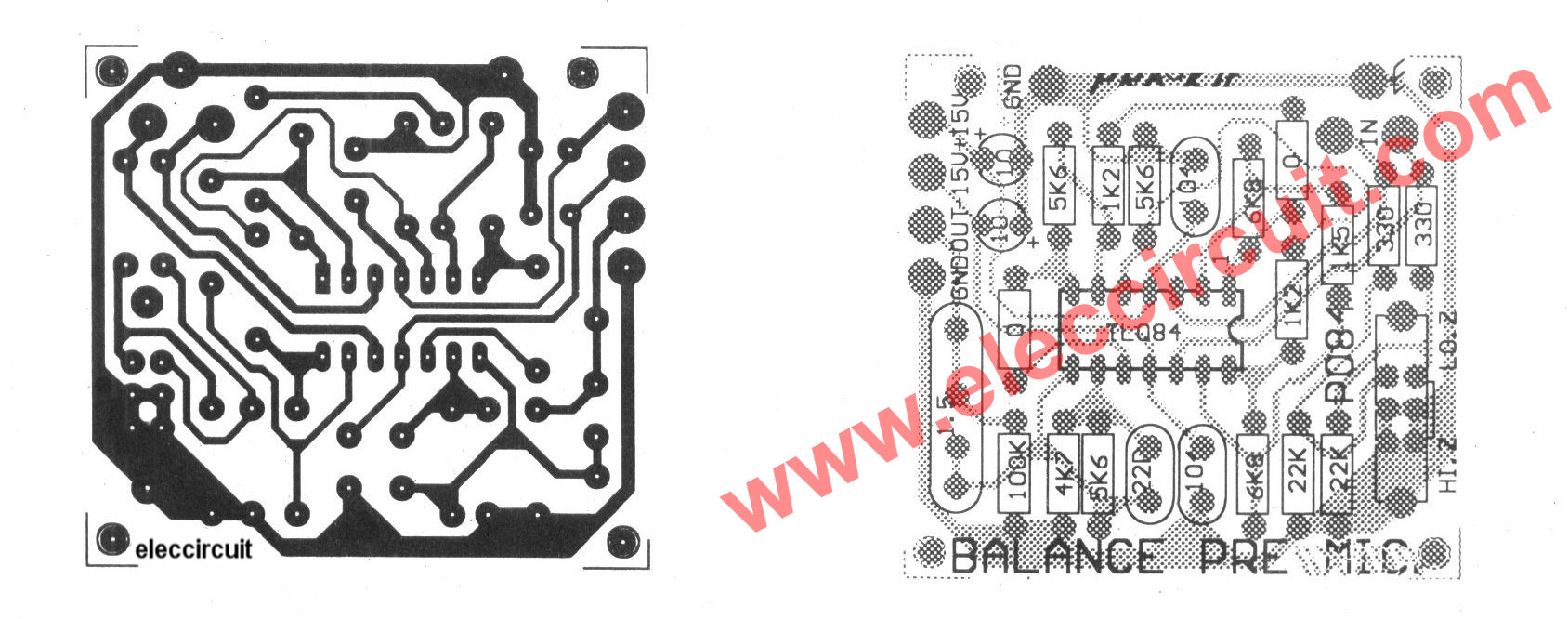
Figure 3 The PCB layout and components layouts of Balance Input Pre Microphone Amplifier circuit
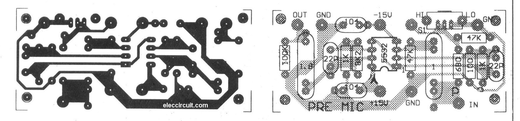
Figure 4 The PCB layout and components layouts of Unbalance Input Pre Microphone Amplifier circuit
Should be used high-quality devices. For example: Metal Film Resistors, Which is a low noise.
All capacitors should be of high quality For example: polypropylene (MKP) or Polycarbonate (MKC) etc.
Parts you will need
BALANCE INPUT
IC1: TL074, Quad Low-Noise JFET-Input General-Purpose Op-Amp
0.25W Resistors tolerance: 1%
R1, R4: 330 ohms
R2, R3: 22K
R5: 1.5K
R6, R7: 6.8K
R8, R8: 1.2K
R10, R11, R13: 5.6K
R12: 4.7K
R14: 100K
Capacitors, Polypropylene (MKP), Polycarbonate (MKC)
C1: 22pF 50V
C2: 1.5-1.8uF 50V
C5, C6: 0.1uF 50V
Electrolytic Capacitors
C3, C4: 10uF 25V
SW: SLIDE 6P
UNBALANCE INPUT
IC1: NE5532, M5218P, OP Amp Dual General Purpose, 8-DIP
0.25W Resistors tolerance: 1%
R1: 680 ohms
R2, R3: 47K
R4: 100 ohms
R5, R6: 1K
R7: 8.2K
R8: 100K
Polypropylene (MKP) or Polycarbonate (MKC)
C1: 1uF 50V
C2, C3: 22pF 50V
C4: 1.5uF 50V
C5, C6: 0.1uF 50V
SW: SLIDE 3P
BALANCE INPUT
Active microphone preamplifier using LF356
This is an active microphone preamplifier circuit for the particular condenser microphone. Generally, the condenser microphone has high sensitivity and the high output signal more than the other types of microphone, but this type needs to have a power supply.
How it works
Figure 1 is a circuit diagram of this project. The condenser microphone M1 need to has a power supply from the current flow through R1 to it that has 2 lead. Its signal will be coupling through C1, R3 to the IC1’s pin 2.
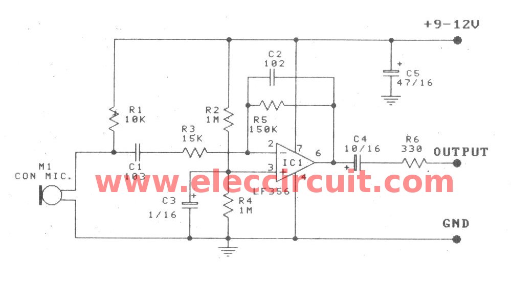
Figure 1 the circuit diagram of this project.
The gain of a circuit will be is determined by R5/R3, this gain is 10 times. The capacitor C2 will offset circuit working to lower the gain when high frequency.
The output at the IC1’s pin 6 will be sent to C4, R6 to other section as we need.
This R2, R4, and C3 are connected together for bias to IC1. So, we can easily use a generally single DC power supply(positive and negative polarity).
The part you need
IC1: LF356 JFET Input Operational Amplifiers (or LF155/LF156/LF256/LF257/LF355/LF356/LF357)
0.25W Resistors, tolerance: 5%
R1: 10K
R2, R4: 1M
R3: 15K
R5: 150K
R6: 330 ohms
Ceramic Capacitors
C1: 0.01uF 50V
C2: 0.001uF 50V
Electrolytic Capacitors
C3: 1uF 50V
C4: 10uF 16V
C5: 47uF 16V
How to builds
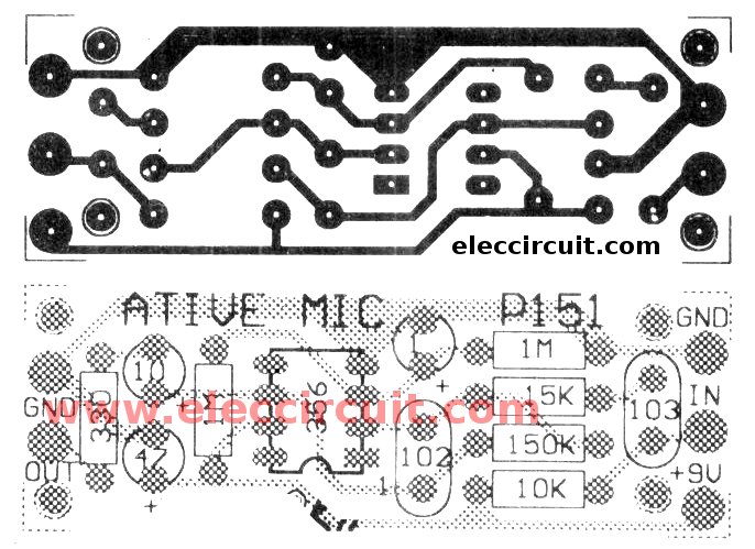
Figure 2 the copper layout and component layout.
This project is smallest so can use the perforated PC board or universal PCB Board and you can build PCB as Figure 2 actual-size of Single-sided Copper PCB layout and components layout
NE5532 MIC Preamplifier 2 channel
This is a Pre Mic circuit or Microphone preamplifier circuit model 2 CH. By this circuit uses integrated number circuit NE5532 or LF353. It perform enlarge sound signal from Dynamic Micro phone give the power goes up for subsequently submit to go to still stereo power amplifier circuit next. This circuit be of good quality good sound, because of use the integrated circuit decreases the noise, but should use the fire feeds +12V GND -12V with. The VR1 and VR2 perform fine decorate the sound.
The detail is other and PCB sees in a picture below.
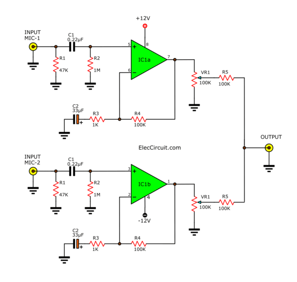
Circuit Pre MIC (microphone preamplifier) 2 CH by IC NE5532 or LF353

PCB Pre MIC (microphone preamplifier) 2 CH by IC NE5532 or LF353
These circuits require DC regulator circuits only. You may use power supply circuits below.
Related Posts


I love electronics. I have been learning about them through creating simple electronic circuits or small projects. And now I am also having my children do the same. Nevertheless, I hope you found the experiences we shared on this site useful and fulfilling.
Awesome Circuit.
Hi Salim Khan,
Thanks for your feedback.
Can i use this circute with Condenser Microphone..
It’s good we learn more thanks
Hello, Kasenge Isaac
Thanks for your feedback.
Have a good day.