If you are looking for a tone generator circuit. First, you will use an IC. Because it is easy and small. But you may use other ideas of the sound generator.

Sometimes, you may like it. Because you may have these components in your store. I love to look at a different circuit. If I have free time, and you?
Here is 4 circuits ideas list:
Simple Warble Tone Generator Circuit
This is a simple warble tone generator circuit. It generates a pulsating sound. We will hear the noise more than a single tone. Both transistors Q2 and Q3 assemble as the tone generator circuit.
Which this frequency modulated with an output of Q1. This frequency generator is a sawtooth waveform.
The Q1 is Programable Unijunction Transistor Or P.U.T (For example, 2N6027 or 2N6028)
The signal can adjust decorate with R7 effectively as want.
When adjusting C1, makes the modulated frequency change, too. We should use a loudspeaker impedance of about 35 ohms.
If we use the lower impedance of the speaker. You should connect a resistor with the speaker in serial. To decrease the sound down.
Or you may take output goes to the input of the power amplifier circuit via capacitor 4 uF.
Recommended: How do SCR works and basic circuits
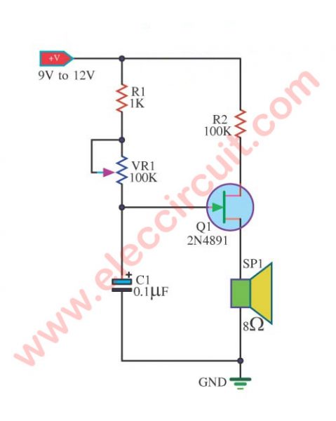
Tone Generator Circuit using 2N4891
This is Basic Tone Generator using UJT Transistor, 2N4891. It can drive a small-sized loudspeaker with the electric bell moderately. The value of C1 is valuable a little to increase the speed in the package and disgorge to load. In each round (Cycle) that get be the sound frequency at shine depart a loudspeaker.
We can adjust the sound frequency using R2 – 100K. If it is low resistance, high frequency. But if it is high resistance, low frequency. This circuit can develop the next version. I hope you enjoy this electric bell circuit.
Read also: 3 Sawtooth wave generator circuits
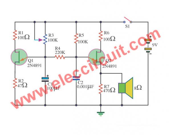
Cricket Generator circuit using 2N4891
This circuit gives sound handful that modifies interestedly, occurrence sound rate cricket Fixed. The R3 should experience change the value C1, R5, and C2 effective that differently.
A loudspeaker should be the piezo Tweeter model. The Transistor use many numbers, Q1 and Q2 are 2N4891 or others.
This circuit requests a 9V power supply(9 volts battery). See other details in the circuit. I hope you fun with this cricket generator circuit.
Read: Let’s try the 3 transistors Audio Amplifier circuits (MONO)
Electronic Bird Sound Circuit
We will learn the operation of the circuit.
When pressed the switch S1. The circuit will work to produce the sound of a bird out to a speaker(sp1). Which the R1, R2, C3 to control transistor Q1 to work rhythmically.
And, the capacitor C4 determines the delay time, for each sounding.
In addition, C2 is the feedback signal. If the C2 is much value, will make the bass sound. However, if C2 is less, will make the treble sound.
When Q1-transistor bias, will have the current flowing through the primary winding of the transformer (T1). Resulting in the induction coil secondary signal to drive speakers.
You may like these circuits, too.
GET UPDATE VIA EMAIL
I always try to make Electronics Learning Easy.
Related Posts

I love electronics. I have been learning about them through creating simple electronic circuits or small projects. And now I am also having my children do the same. Nevertheless, I hope you found the experiences we shared on this site useful and fulfilling.


I love your English.
Hi Mimi
Thanks for your feedback.
nice cirquits
I need the transister.circuit of
ice cream vender. sound.