This is an Infrared Intruder Alarm circuit that interesting. Imagine some people walk through restricted areas. At that moment, this circuit immediately sounded to alert you.
It uses the principle of cut the infrared light. The circuit will recognize, control relay runs, and turns on a warning signal like a siren for us to hear.
This circuit is suitable for learning infrared operations. Or, we can apply other controls Because of using a relay.
It uses the general parts you can buy easily in a local store near your house.
Sound good, doesn’t it? Want to know how?
How it works
Look at the circuit below.
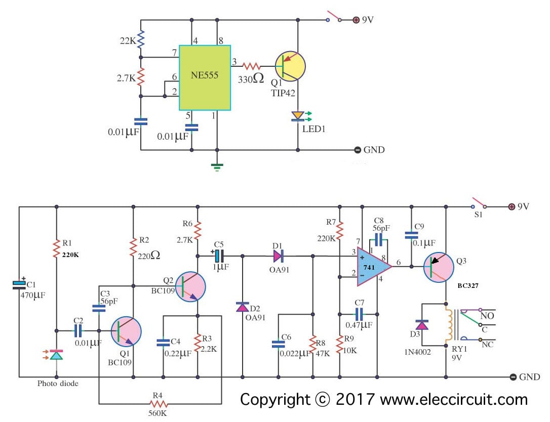
This circuit consists of 2 major parts, transmitter and receiver.
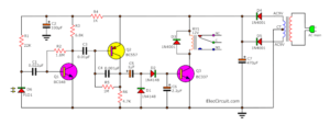
Transmitter
It is an Infrared signal transmission sector. Use a few parts.
Look: an infrared LED is a special LED. When we power to it. We cannot see light. But can use it. It will emit infrared light. If uses a pulsating DC voltage. It can spread the light radius better than stable DC.
Use The 555 timer and others produce a varying DC voltage. It is a square waveform high-frequency output, 5kHz. And using power transistor- TIP42 to crease a current up to the infrared LED. May have a radius of up to 15 meters.
Receiver
Let’s see the infrared receiver section below of the circuit.
We use a photodiode to receive infrared light. Or use the phototransistor or the infrared module.
Which is better?
I think the last one is the best. Because it is so easy. The module has a preamplifier inside.
However, this circuit uses just a photodiode (it is an old circuit). So, we need to use a preamplifier to increase a signal from the photodiode.
Then, transform it into DC voltage by D1, D2, R8, and C.
This signal is still weak. We need to boost up to higher by 741 op-amps or CA3130. And enough signal comes out of pin 6.
But Q3 does not work. Because it is a PNP transistor. So, the relay does not work too.
Not only that,
After that, we try to conceal the infrared beam. So, No output signal to a base of Q3. But It is a biased base of the PNP transistor.
With this why Q1 drive relay pulls in contact to turn on a siren or your load runs.
This circuit uses a 9V power supply as a power source. Should use a DC regulator to limit any noise.
Parts you will need
All Resistors 0.25W, Tolerance 5%
Transmitter
IC1: NE555 Timer
R:22K
R:2.7K
R:330 ohms
Q-TIP42, PNP Transistor
C: 0.01uF 50V Ceramic capacitor Infrared LED
Receiver
Q1,Q2 BC109 NPN transistors
Q3: BC327 PNP transistor
IC: CA3130
RY1: 9V 1 Contact Rely
Electrolytic Capacitors
C1: 470uF 16V C5: 1uF 50V
Ceramic Capacitors
C2: 0.01uF 50V
C3, C8: 56pF 50V
C4: 0.22uF 50V
C6: 0.022uF 50V
C7: 0.47uF 50V
C9: 0.1uF 50V
D1, D2: OA91 Diodes
D3: 1N4002 Diodes
R1, R7: 220K
R2: 220 ohms
R3: 2.2K
R4: 560K
R6: 2.7K
R8: 47K
R9: 10K Photodiodes
Conclusion
Note: This circuit is gradually incomplete. So, you need to sure to make it. However, It is a good teacher for those who love to learn Electronics.

I love electronics. I have been learning about them through creating simple electronic circuits or small projects. And now I am also having my children do the same. Nevertheless, I hope you found the experiences we shared on this site useful and fulfilling.