What is a temperature sensor diode? Well, it is just a general silicon diode. But when the diode is in forward bias, the resistance of the diode changes depending on the temperature. There exists a thermistor, which is a type of resistor made for this task, and it is more convenient to use.
However, we want to use the diode to learn about the change in conductivity of semiconductors depending on temperature. In fact, all semiconductors can be temperature sensors.
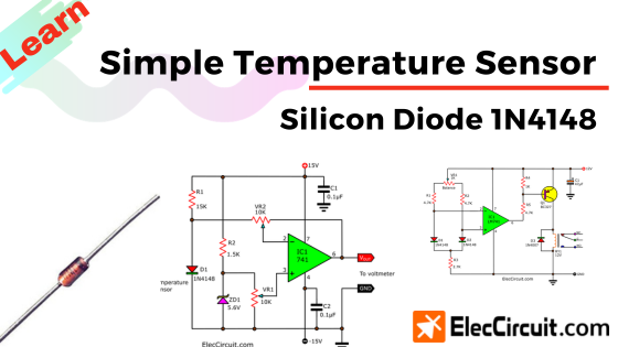
Experiment with 1N4148 diode temperature sensing
All semiconductors have resistance. Its resistance will reduce when it is hot; it is also true in the opposite way: when it is cold, its resistance will rise.
We can use all kinds of semiconductors, such as transistors, ICs, SCRs, etc. But in this circuit, we will use the 1N4148 diode. Because it is easy to use, cheap, and in stock all the time.
How it works
In fact, when the diode is forward-biased, it has a voltage across it of about 400mV to 500mV at a current of about 1mA. This voltage level depends on the current and the substance used to make these diodes.
In a silicon diode, the voltage across it will reduce by about 2mV per degree Celsius. So we can use it here. You can also use a transistor, a diode bridge, and more. They are also silicon-based semiconductors.
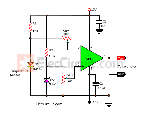
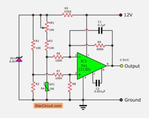
The circuit below is a simple temperature sensor using a 1N4148 diode.
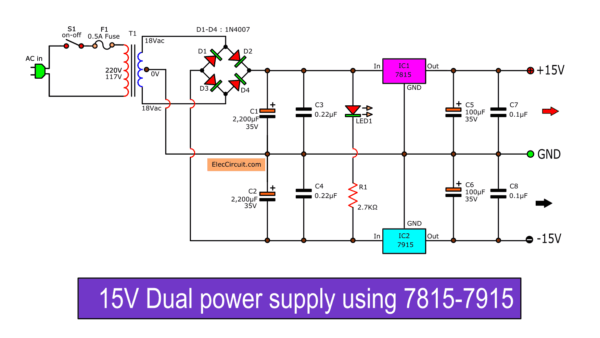
But first, let’s get ourselves a steady-voltage power supply. The Dual +15V/-15V DC Regulator is the most suitable for this.
A constant current will flow through R1 to D1. And when the temperature of D1 changes, the voltage across it changes. But the change in voltage is too low that a normal voltmeter cannot even detect it. So we need the help of the comparator.
We chose the LM741 OP-AMP IC and set it to an inverting comparator function. Why this function? Since we need the output voltage to increase as the temperature does.
Suppose that the temperature is 20 degrees Celsius, which makes the output voltage 2.00V. But if the temperature rises up to 30 degrees Celsius, the output voltage should rise to 3.00V as well.
When the temperature is high, the voltage across D1 (Vin at pin 2) is lower than the reference voltage (Vref at pin 3) from R2 and ZD1. Causing the output voltage (pin 6) to switch from low to high.
On the other hand, when the temperature is low, the voltage at pin 2 is higher than at pin 3. So, pin 6 switches to low.
Do not worry if you do not understand it now. Just knowing how to use it is enough. And your skills will improve over time; we believe in you.
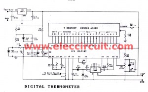
Also, we need to use VR1 and VR2 to tune the right output for a certain temperature. We will be using the digital thermometer to compare the current temperature to the output reading from the voltmeter.
For example, if the room temperature is 29 degrees Celsius, then we adjust VR1 and VR2 until the output voltage reads 2.90V on the voltmeter. So when the temperature increases to 35 degrees Celsius and the voltmeter does not read 3.5V at the output, we will need to adjust VR1 and VR2 until it is 3.5V.
Note: Your digital multimeter may have a thermometer built into it.
And you may use a piece of ice and hot water in the tuning process. But the leg of the diode cannot be in contact with the water.
However, this circuit is not 100% accurate. It is just good for learning science through experiments.
See other simple electronic circuits
Using Single Power Supply for Op-Amp
Sometimes using the dual voltage regulator circuit above can be inconvenient. We can try using a single power supply in two ways, which are:
First: Connect pin 4 (negative power supply to ground), See below.
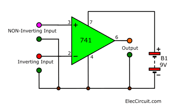
The op-amp will also operate from a single power supply. Learn how to use 741 op-amp
Second: Use the Power Supply Splitter circuit using Op-amp. You can use 12V input to +6V, -6V, and ground for the Op-amp.
I would rather recommend you learn the first method. Because it is more convenient and effective according to your needs. See an example below.
Differential temperature controller
If you need to control two things at the same temperature. You should look at a Simple Differential temperature controller circuit diagram. It will turn on the relay switch when both temperature sensors are different.
Some people call that the Balance temperature switch. You may use it in other ways up to you.
Why should you build it?
- It uses a few components
- It is an old circuit that uses general parts so easy to buy.
- You can learn basic electronics through it.
How it works
In the circuit, we use the main components, 741 op-amps, silicon diode, and relay.
Also, I use the temperature sensor Diode, 1N4148. You may read it first.
Then, back to see the circuit again.
- D1 and D2—both diodes are the temperature sensor.
- IC1-LM741—is a comparator circuit. The gain of the IC1 is very high in open-loop mode.
- Q1—driver transistor to control a relay.
- RY1— Turn on-off the loads.
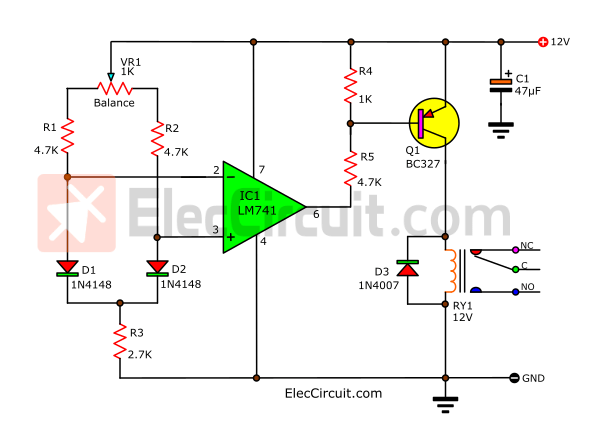
Differential temperature controller circuit diagram
First, The diode sensor gets a forward-biased current. Then, there are the current flows through VR1, R1, R2, R3. We adjust VR1 to set the current, and flows of both diodes to be the same temperature.
When both diodes get a different temperature. The voltage across them also are different. Which this different voltage will come to the input of IC1, the voltage comparator.
Second, If the voltage across both inputs(pin 2, 3) is just slightly different. Then, a high voltage comes out of pin 6.
Third, the base of Q1 has a bias current, it is working to drive a small relay to be on. If D1 is hotter than D2, the relay will turn on.
Last, the contact of the relay is closed, the current can flow. To turn on the other external devices such as the solenoid, coils, lamps, and more.
The setting of the circuit
This circuit requests a steady voltage power supply, 12V. In the process of setting. We must place two diodes at the same temperature. Then, adjust VR1 to close the points of the balanced circuit. By the op-amp is not working. If both diodes get a different temperature. The relay turns on.
Next, we test to place your fingers or other heat things to catch diode-D1. The Voltage drop across D1 and pin 2 is low. It makes the voltage at pin 3 is higher. The relay will work.
The diode sensor D1 is the main. If it is hotter than D2. The voltage across it is lower than D2. The output voltage of IC1 is LOW.
So, the base of Q1 is low, it is on. Because it is a PNP type. Thus it drives the relay to work, too.
But Experience, we cannot keep the temperature in the holding. It just makes the temperature of the coils very similar.
Which preset temperature may be increased indefinitely. Up to the maximum coil temperature heat can be produced up.
Also most electronics components, using a higher temperature, have a shorter lifespan.
Hand-picked related articles you may want to read:
- Simple temperature to the voltage converter circuit
- Digital temperature meter using LM335 or LM135
- How do SCR work and basic circuits
This circuit requires enough power supply. Do you have this one? If you do not have it. Look: A lot of Power supply circuit
GET UPDATE VIA EMAIL
I always try to make Electronics Learning Easy.
Related Posts


I love electronics. I have been learning about them through creating simple electronic circuits or small projects. And now I am also having my children do the same. Nevertheless, I hope you found the experiences we shared on this site useful and fulfilling.
Hello it’s a shame to have to use a +15 -15 power supply for the temperature sensor. Could you show an assembly only with + 12V? Thank you and congratulations.
Hello Didiersee
Thanks for your visit. I am happy that you want to try these circuits. It is good learning for temperature sensors using Diode silicon.
I believe you will test the circuit well.
Please back to read again: https://www.eleccircuit.com/measurements-temperature-by-diode-1n4148/#Using_Single_Power_supply_for_Op-Amp
Do not forget to share me when you test it.
Thanks
Apichet
Hello very help full article, i was wondering if the same circuit could be used to make an weadstone temp compensated air velocity sensor..
1 diode as temp.sensor and the other as hot diode as velocity sensor…
Greets Call
This is my first time visit at here and i am
tгuly impressed to read all at single place.
Thanks