If you are looking for a simple frequency divider circuit. This circuit may be suitable for you.
It is designed to divide a frequency of input signal into just half.
Then, it goes out of the output.
The advantage of this circuit is a small circuit. It uses just a transistor only and other few components.
So cheap and get easily all components.
How does it work
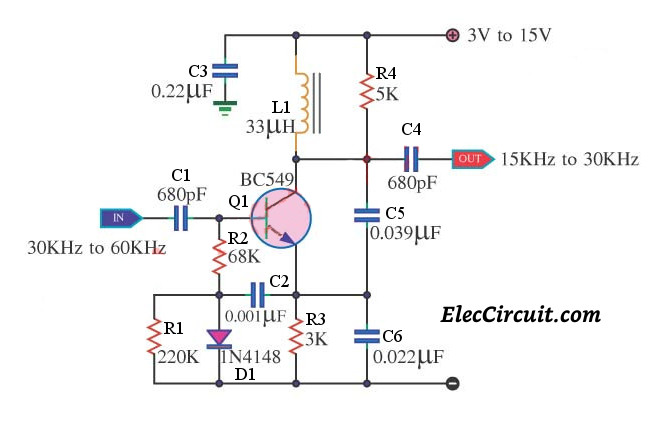
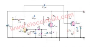
Since the transistor-Q1 (BC549) gets a biased current in non-active status. So, It is active only in the range of input is positive voltage only.
This circuit uses a main idea from the common-base Colpitts oscillator model. The Colpitts circuit looks like other LC oscillators.
The simple circuit consists of a bipolar transistor with its output connected to the input, in a feedback loop. Which contain a parallel LC circuit.
The parallel LC circuit is called a tank circuit.
The tank circuit consists of L1, C4, and C5. They can set the frequency is about 16.5 kHz.
When input single of 30kHz-60kHz comes to the input of the circuit. The circuit will lock, generate the oscillator in a range frequency of 15kHz – 30kHz.
The other details, please see in the circuit. Good luck!
Parts you will need
Semiconductors:
- Q1: BC549, 45V 100mA NPN Transistor
- D1: 1N4148, 75V 150mA Diode
0.25W Resistors, tolerance: 5%
- R1: 220K
- R2: 68K
- R3: 3K
- R4: 5K
Ceramic Capacitors
- C1,C4: 680pF 50V
- C2: 0.001µF 50V
- C3: 0.22µF 50V
- C5: 0.039µF 50V
- C6: 0.022µF 50V
L1: 33µH coil
GET UPDATE VIA EMAIL
I always try to make Electronics Learning Easy.
Related Posts

I love electronics. I have been learning about them through creating simple electronic circuits or small projects. And now I am also having my children do the same. Nevertheless, I hope you found the experiences we shared on this site useful and fulfilling.