We like a multi voltage power supply circuit. It has 2 dual output,5V and 12V. There is positive, negative and ground. All has 1A max current.
- The 12V are +12V,-12V, Ground
- the 5V are +5V, -5V, Ground
It is proper common analog and digital circuits.
Sometimes, we use only 5V or 12V does not enough. We need to have many voltage terminals. The equipment it easy to buy and affordable.
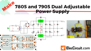
12V, 5V Dual Regulator circuit using ICs
First of all, the transformer-T1 reduces AC voltage from 220V or 170V (US) down to about 15 volts. Next, the AC goes to D1 through D4, full wave bridge rectifier, act as a rectifier AC to DC.
Then there are capacitors -C1, C2, C5 and C6 to smooth the Pulsed DC into a certain DC voltage, unregulated.
It flows through to the pin 1 (Vin) of IC1 and IC2, DC voltage regulator. Which IC1 (LM7812) will keeps fixed output voltage to reduce of + 12 volt. And also IC2 (LM7912) is negative fixed voltage regulator to -12 volts through the pin 3 (Vout) of IC1 and IC2.
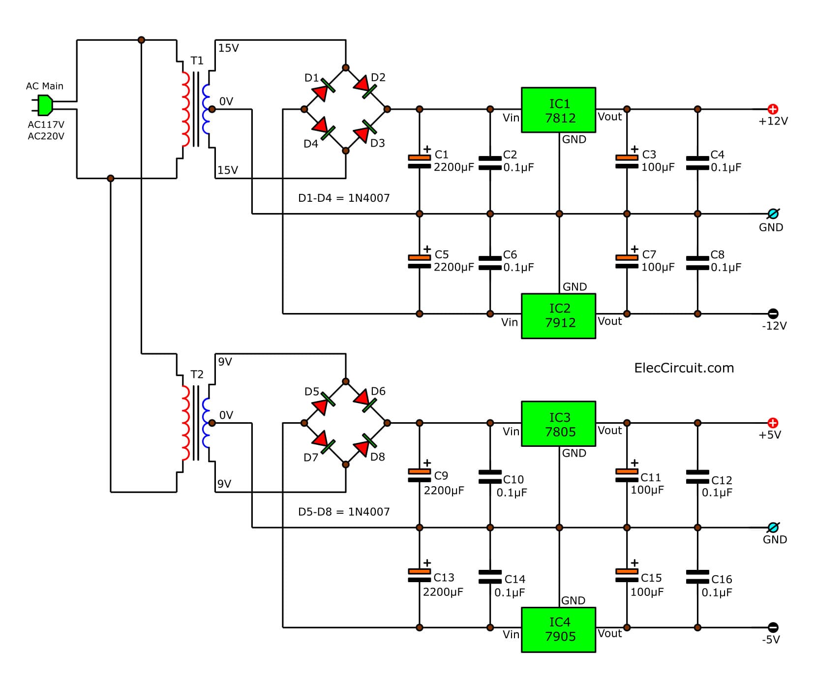
And there are more capacitors C3, C4, C7, and C8. To filtered to low ripple voltage. This part we have the output voltage regulator at +12 volts and -12 volts.
When T2 reduce the AC voltage from 220 volts down to 9 volts. And D5 through D8 diode is bridge rectifier to change the AC to DC Cpulsed DC).
After that, these capacitors C9, C10, C13, and C14 will smoothes (filter) from the pulsed DC to a steady DC voltage.
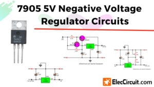
Then the current flow through to the pin1 (Vin) of the IC3, and IC4. By IC3 (IC-7805) is a positive voltage regulator IC, 5V fixed output.
Learn more 7805 Datasheet and example circuits
And IC4 (7905) is negative voltage regulator IC,-5 volts fixed output at pin3. And then flows to more smoothing with C11, C12, C15, and C16. Which the output voltage of +5 volts and -5 volts are suitable for a most digital circuit that uses 1A max.
Be careful 79xx pinout
The 79xx series, we don’t use it often. can be confusing. See pinout below.
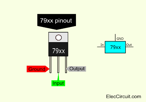
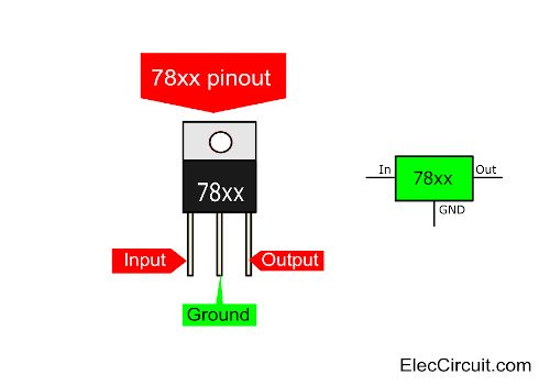
79xx pinout and see 78xx series, they are familiar.
15V, 30V, 45V, 60V Multiple output Power supplies using Zener and transistor
Friends ever meet a problem experience Electronics Circuit at want the level Voltage various?
I like to make any circuits form old electronic parts,Because it is very cheap, and a great challenge. Today I begs for to suggest Muti lab power supply 15V,30V,45V,60V Circuit may meet the requirement of friends get.
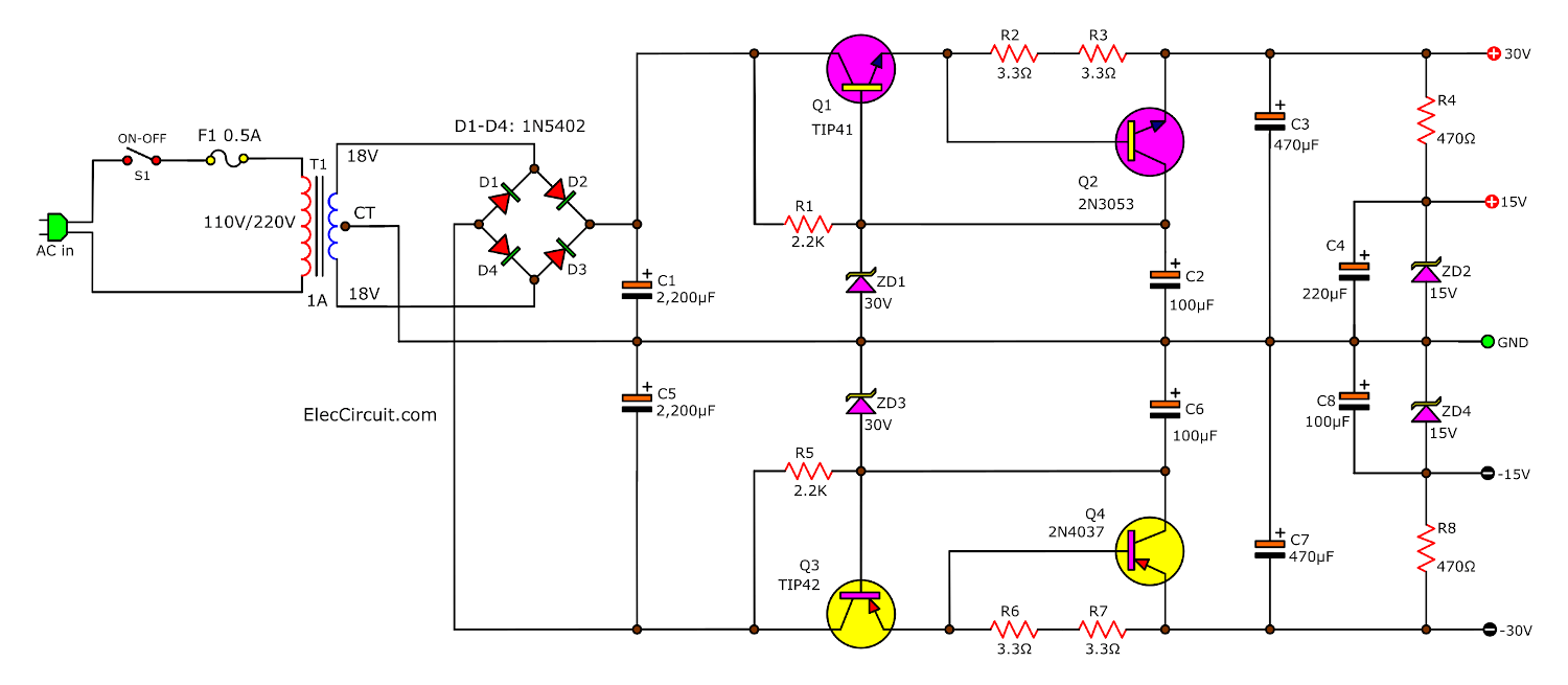
By it is the circuit is simple use the transistor = 4 pcs (C1061, A761, Driver 2N3053, 2N4037) only and We use a Zener diode 30V (2pcs) has a constant voltage level. The transistor have equiv number many the number. but however this circuit inappropriate for you who want current tall. Because it gives current 0.5A only just. This circuit idea friends, may apply the work has please yes.
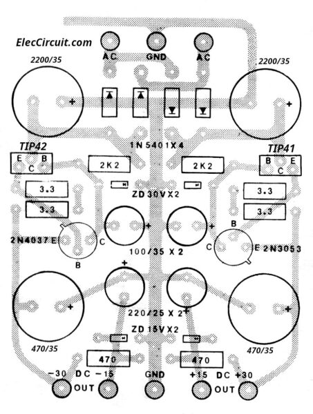
PCB Layout of multi-lab power supply 15V,30V,45V,60V
Simple multi voltage step down converter circuit
This is a simple multi-voltage step-down converter circuit. You can set multiple DC Output Selection 3V, 6V, 9V by the selector switch. It is a fixed 200mA Regulator. Though it is very easy, it is still interesting for learning. Sometimes you may use it.
This circuit will generate a smaller DC output voltage from a larger DC input voltage.
It is quick and simple to make. By changing the value of the Zener diode. The circuit can universally adapt to provide other output voltages.
The working circuit
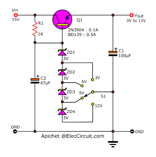
The multi voltage step down converter circuit
This circuit has a difference from the Zener diode regulator circuits. First of all, we use many the Zener diode in series. A chain of 3V Zener diode increases the output by +3V for every diode used.
It can maintain the regulated Vout at any level, as we choose on the selector switch.
- 3V the voltage across only from ZD1
- 6V volts ZD1+ZD2 (3+3)
- 9V, the voltage across ZD1+ZD2+ZD3 (3+3+3)
- 12V the voltage across ZD1+ZD2+ZD3+ZD4 (3+3+3)
Next, Suppose that the 15V input voltage flow to a resistor-R1, the base of Q1 2N3904. To bais Q1-2N3904 works. Then, the large current flow from collector to emitter of Q1 to the output.
At the same time, the series of Zener diodes also connect to the base of Q1.
Thus, the output voltage has stable. And the current is higher than using only the Zener diode.
Final, Capacitor-C1 will smooth (filter) the pulsating voltage at the output power supply into a steady direct current (DC).
Parts you will need
Q1- 2N3904 – 0.2A 40V NPN transistor
?You may use BD139 to increase the output current more than 0.5A
R1 – 1K 0.5W resistors
ZD1 to ZD4 = 3V 0.5W Zener diodes
C1 – 100uF 25V Electrolytic capacitor
C2 – 47uF 25V Electrolytic capacitor
Also multi voltage step down converter
Also Multi voltage power supply circuit
Convert two-level DC voltage 5V, 12V They use a base of LM7805-IC, For digital and analog that use current lower than 1 amps.
GET UPDATE VIA EMAIL
I always try to make Electronics Learning Easy.

I love electronics. I have been learning about them through creating simple electronic circuits or small projects. And now I am also having my children do the same. Nevertheless, I hope you found the experiences we shared on this site useful and fulfilling.
I Want To Make This Project “Multi voltage power supply circuit using IC-78xx series”
Please Help With The Procedure Soon And Downloadable WriteUp Material
79×× pin details are correct
Hello Shanmuga Sundharam,
Thanks for your feedback.
Have a good day.