We have many ways to make the function generator. Using NE566/LM566 is a good choice. Because it easy to use. It looks like a NE555 timer.
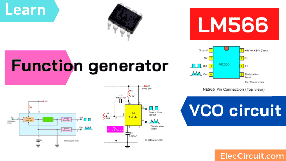
And we often use the NE566 as Voltage controlled oscillator or VCO circuit. It is a type of oscillator. We can control the frequency of the output with the amplitude of an input voltage signal.
FEATURES
- Wide range of operating voltage (up to 24V; single or dual)
- High linearity of modulation
- Highly stable center frequency (200ppm/°C typical)
- Highly linear triangle wave output
- Frequency programming by means of a resistor or capacitor, voltage or current
- Frequency adjustable over the 10-to-1 range with the same capacitor
Learn: How to use 555 timer circuits
APPLICATIONS
Here are examples using them on a lot of applications.
- Function generators
- Tone generators
- Frequency shift keying
- FM modulators
- Clock generators
- Signal generators
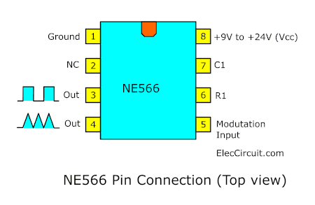
NE566 pinout
It has the same shape as NE555 on DIP8. But the legs are used differently. Let’s see the NE566 pinout below.
Block diagram
What is VCO? Look at below.
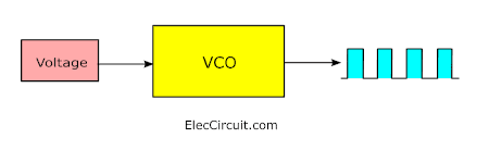
It is a VCO (voltage-controlled oscillator) of linearity with buffered square wave and triangle wave outputs.
Look at the block diagram inside NE566 IC.
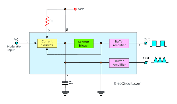
We can control the frequency of oscillation by an external
resistor(R1) and capacitor(C1) and the voltage applied(VC) to the control terminal.
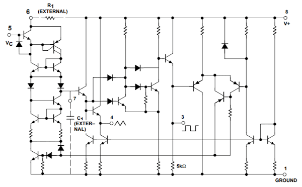
The oscillator can be programmed over a ten-to-one frequency
range by proper selection of external resistance and modulated
over a ten-to-one range by the control voltage, with exceptional
linearity.
You probably want to use it. And of course, the circuit examples are always a wonderful assistant to our good understanding.
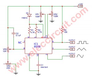
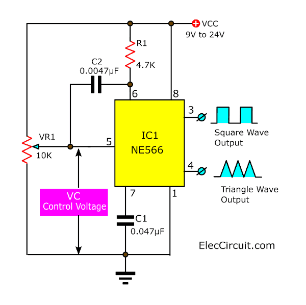
Function Generator circuit
This is a simple Function generator circuit on two waveforms. The important part of the circuit is LM566 or NE566. It produces Sawtooth(Triangle) and Square waves from 1Hz up to 1MHz. The amplitude of the voltage offset and duty cycle is adjustable to offer a wide range of generated signals.

We use VR1 to adjust a control voltage (VC) to control the output frequency oscillator. We can find the center frequency (F)
F = 2 (Vcc – VC)/ (R1 C1 Vcc)
The power supply voltage is 9V to 24V.
Conclusion
NE566 or LM566 is a general-purpose voltage controlled oscillator that highly stable, easy to use.
It produces Triangle and Square waves. R1 and C1 control the center frequency and the voltage at pin 5.
Note:
- The level of output will not drop to 0V.
- If 12V power supply (pin 8) the triangle waveform will be 4V to 6V and the square wave will be between 6 volts to 11.5 volts.
Check out these related circuits, too:
- Simple VCO using Schmitt trigger using 74HC14
- Universal tester circuit with VCO(voltage controlled oscillator)
- XR2206 function generator circuit
GET UPDATE VIA EMAIL
I always try to make Electronics Learning Easy.
Related Posts

I love electronics. I have been learning about them through creating simple electronic circuits or small projects. And now I am also having my children do the same. Nevertheless, I hope you found the experiences we shared on this site useful and fulfilling.
i need an emergency help for vco 566 with microphone pls contact
Hi,
Thank you for visiting our website. I can’t respond to your urgent request because I’m not good enough to do quick circuits. I’m sorry. My dad is currently not available to do this circuit. However, in the future, I think I might learn this circuit, it’s interesting, hope you will continue to follow our website. 🙂