A Logic probe is useful tool to measure. In checking digital circuits.
As a meter, which is used to measure power in electrical circuits.
The Logic probe will detect a logic “1” and “0” or pulse in a digital circuit.
It has a handle and head.It has a pin to measure a different parts of the circuits or IC pin.
And there are LED display to show a digital state as a “1” or “0” or pulse.
Before use, we will connect the two wires to a power supply terminal. To power the its circuit.
They can be used both TTL and CMOS system.
I collect a many types of logic probe circuits. You can build easily them.
Read Related : Learn simple AND and OR logic gate without IC
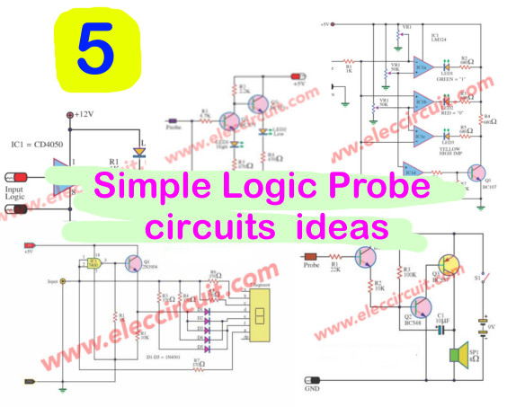
There are 6 circuits, as follows.(see below!)
Circuit 1# Simple Logic Probe using IC-4050
If you want a logic probe circuit that easy and save money. This circuit may be best choice.
I interested circuit. It is cheap Logic probe using 4050. It name is CMOS 4050 or CD4050 or LM4050.
Which is the integrated circuit of not gate buffer logic. I use just one part or 1/6 only.
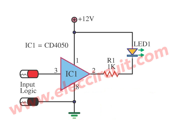
Look at the circuit.
The LED will grow up when input is low “0” logic only.
Circuit 2# Logic Digital Tester using LM324
This is TTL Logic Digital Tester Circuit. And can use for CMOS at level input about 5V.
Look at the circuit
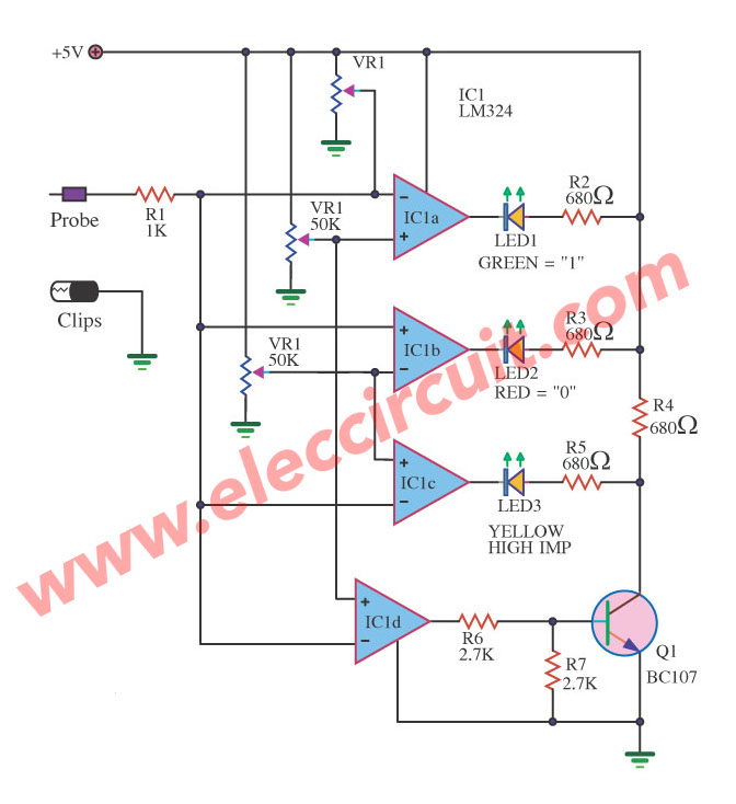
We use the integrated circuit LM324 as key circuit. They drive All LED display.
It requires very low current of about 10mA. There is potentiometer to adjust a gain of 3 level logic digital. As follows.
- The green LED is high level logic.
- The red LED is low level logic.
- The Yellow LED is high IMR
The detail is other please look at the circuit.
Circuit 3# Mini Logic probe with transistor circuit
If you are looking for a simple transistor logic probe circuit. This may be one good chioce.
It is suitable for checking the voltage levels in the TTL circuit.
There 2 LED displays to shows high and low logic level.
Look at the circuit.
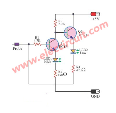
When the input voltage to the probe tip is higher than 2.1 volts (state logic “high”).
Transistor Q1 will drive the light emitting diodes (LED) LED1 with direct bias. It glows up to show the logic “high”(high).
And the collector voltage of Q1 is low voltage.
So, Q2 does not work. Because base-emitter of transistor Q2 is low status. And LED2 does not glow up, too.
If the input voltage changed to 0 volts (low level logic). Then Q1 is not the current bias is not working.
Then, the current flows through R2 to base of Q2. So, it runs. To drive high current to LED2 glow instead LED1.
Recommended: 4011 Tone Generator circuit projects
Circuit 4# LED status TTL logic High-Low circuit
This is a digital logic probe circuit. Why it special than other circuit? It can show a “H” or “L” on LED 7 segment display. So, clearly display text, easy to see the value.
Since, it requires 5V power supply. so it is ideal for TTL digital.
Operation of the circuit
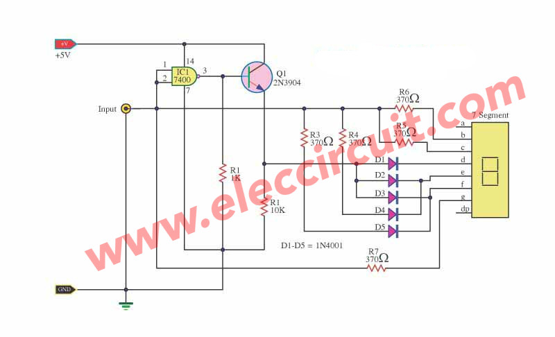
Look at the circuit below.
In normal state, the input is Low. And IC1 which is nand gate into not gate. Then, the ouput of IC1 is high status. And Q1 works with voltage drops across R2.
Then, the high voltage comes to the diodes D1, D2, D3. To drive the LED 7 Segment to display the letter “L”.
In contrast, if the input is high voltage. It makes IC1 change the status is “Low”.
So, the Q1 does not work. But some signal flows from the input through R5, R6 to LED 7 Segment. And other signal via R3, R4, D4, D5 to LED 7 Segment too.
It so show the display letters “H”.
And the circuit will have a resistor R7 is connected too. To help reduce the current flow to the LED 7 Segment. It will protect any damage.
Note:
We may cannot buy 7400 TTL IC. It is not worry. You can use TTL 74LS00. I apply to this circuit is very simple and cheap as well.
Circuit 5# Sound logic probe using transistor BC557
Imagine you’re not comfortable with the LED display in any case.
Is it good? If we use tones as a result (high or low status) instead.
Look at the circuit
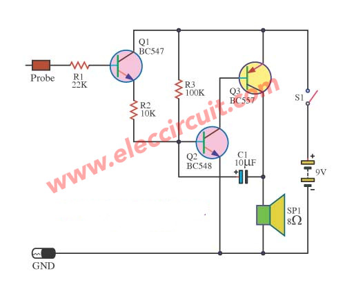
It uses a few parts. So cheap and easy.
We use a tiny speaker to emit different tone sound rate(fast and slow).
The two-transistor in circuit (No. BC548 and BC557). They are a simple astable Multi vibrator.
The tone or frequency can determines by a 100 kohm resistor and 10 uF capacitor.
And, the speaker serves as a load of Q3 transistor BC557. The current flows from emitter- collector and SP1 to ground(negative).
BC547 transistor and a resistance of 10K in parallel with a resistor 100K.
They will detect a level of voltage.
If it is a high state (high) BC547 will work. And the repetition rate increases. It control a high frequency on output.
Read next: On-off SCR control circuit with logic gate IC
Circuit 6# 3 State Logic Tester Probe Circuit Using CD4001
This is a three state logic probe circuit.
Circuit operation
This circuit will use Nor gate IC, CD4001. In controling LED display.
In case of still have no input signal comes. The input pin of IC1/1 keep float. It makes a lot of impedance. Which it no LED light up.
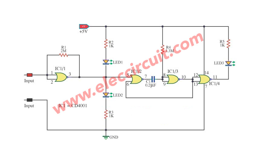
In first case: If input is “0”.
The IC1/1 will change status the output is “1”. It makes LED1 go out. But LED2 light up.
The status at pin 5 of IC1/2 will be “1”. It makes pin 7 of IC1/2 is “0” at all time.
It causes IC1/3 and IC1/4 work to pin 11 of IC1/4 is “0” makes LED3 light up.
In second if input is “1”.
The IC1/1 will back status the output is “0”. It makes LED1 light up. But LED2 goes out.
The IC1/2 will get input is “0”. It makes IC1/2, IC1/3 work. They are a frequency generator or oscillator circuit to IC1/4. To drive the current for LED3 and it flashes.
In third case, if input is pulse.
It will be both Low and High status alternately. It makes LED1 and LED2 light up alternately as speed of that pulse. And LED3 will light up at all time.
Conclusion
These circuits are interesting concepts. Hope that friends can use it. Some circuits I have never actually tried.
Therefore there may be a mistake. If you try and get any results. Please share with us.
Here are a couple of related articles you should read, too:
- On-off SCR control circuit with logic gate IC
- Logical guessing game circuit
- 8 simple touch switch circuit projects
GET UPDATE VIA EMAIL
I always try to make Electronics Learning Easy.
Related Posts


I love electronics. I have been learning about them through creating simple electronic circuits or small projects. And now I am also having my children do the same. Nevertheless, I hope you found the experiences we shared on this site useful and fulfilling.
This is a good collection of Logic Probe Designs..Nice Job My Friend!!!!
So Many Great Digital Logic Probe designs Can Ve Found Here!!! Awesome,,I Love Them All!!!!
Completely useless. Learn some English!
Hi,
Thanks for your feedback.
I will try to improve my English grow.